Table of Contents
- 1. Electricity management and RCP
Plan electricity management

- 1. Electricity management and RCP
This article describes installation planning. For on-site implementation and equipment configuration on the Climkit Platform, refer to the links at the end of the article.
1. Electricity management and RCP
Climkit's electricity management solution consists of providing meters to measure and read electricity consumption, transmitting data to the platform and activating one of the available operating methods, such as generating Individual statements or automatic billing to consumers.
The solution is generally applied within the framework of a self-consumption community (RCP).
It can also be used in other contexts, for example:
- In a commercial building to distinguish the consumption of different surface areas
- In a campsite or a port to account for consumption by pitch
- In any situation requiring the measurement, accounting and billing of electricity consumption
Standard connection diagram for an RCP
There are several connection modes for electricity meters and communication depending on the number of consumers and buildings on a Site.
The standard scheme consists of an RCP with:
- A single point of introduction to the network with a DSO input meter
- Multiple consumers (apartments, offices, common areas, etc.) connected to private meters.
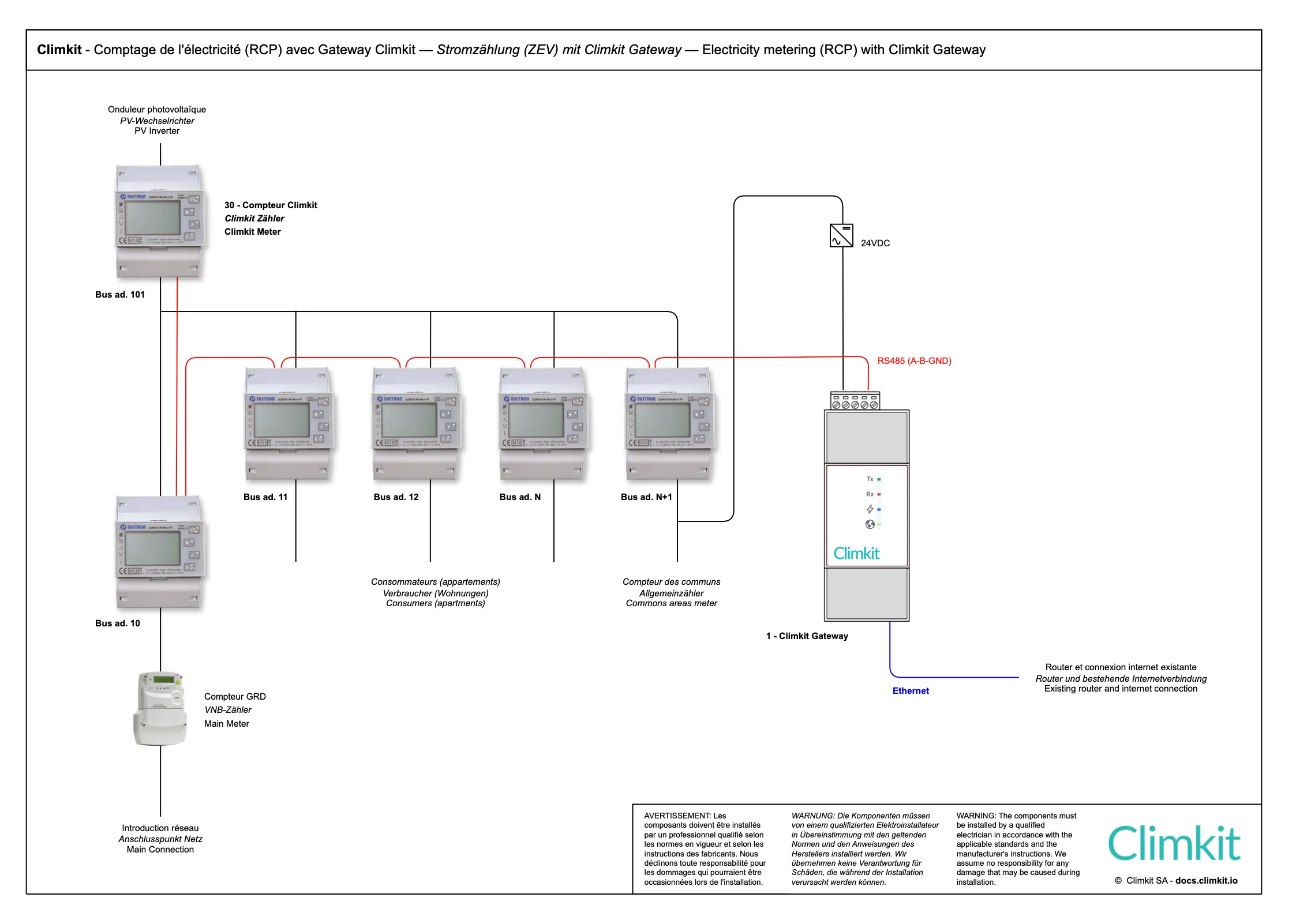
Electrical connection
The diagram above shows the case of an RCP with a single DSO meter at the electrical input of the building.
Consumers such as apartments and common areas are measured by private meters.
A private meter also measures the photovoltaic production (inverter output).
A private meter is also installed at the input in series with the DSO meter.
The number of meters depends on what needs to be measured and billed separately. Here is a list of the most common meters to consider:
- Heat pump: to distinguish its consumption from the rest of the common areas
- Electric vehicle charging stations
- Battery connected in AC (and not in DC via a hybrid inverter)
- Photovoltaic inverters: one meter per installation allows for measuring their performance separately and detecting potential problems more easily.
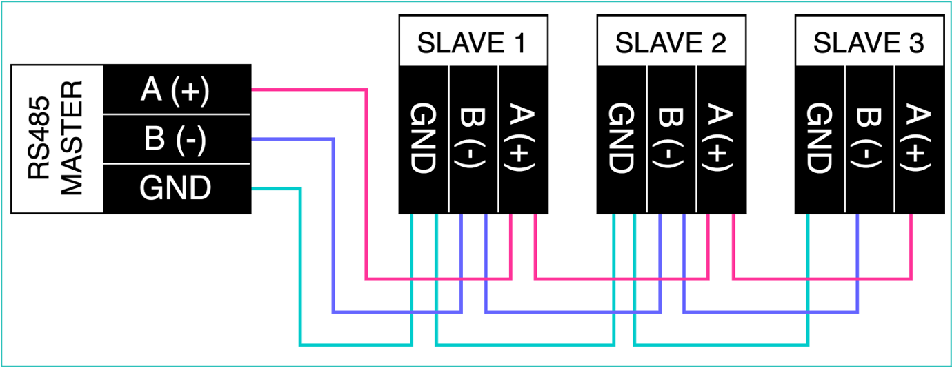
RS485 communication bus and internet connection
A serial communication bus of type RS485 connects each meter to the RS485 interface of the Climkit Gateway.
The meters (Slaves) are connected by an RS485 bus network to the Gateway (Master) according to the diagram below.
Guidelines and recommendations for cable pulling:
- Use a shielded U72 type cable (aluminum foil type) 4 × 0.8 mm².
- All devices must be connected in series (daisy-chain). Avoid branches, stars, or T-connections that can generate communication failures.
- The cable must not form closed loops.
- Maximum length: aim for < 500 m for a safety margin.
- Avoid passing near equipment that could create interference (motors, drives...).
The Gateway is itself connected via its Ethernet interface to the 4G Router equipped with a multi-operator SIM card to allow remote meter reading.
Climkit Offer
The standard Climkit offer includes the elements necessary for the system's operation: hardware equipment, software features, as well as services related to the setup.
All hardware is provided preconfigured to simplify installation and ensure proper meter communication.
- Equipment:
- LAN router or 4G Router
- Climkit Gateway
- Electricity meters
- Software features:
- Reading and visualization of electricity meters
- Setup service:
- Technical coordination and verification of meter readings
- Administrative setup
All products are ordered directly from Climkit.
In most cases, the installation can be carried out by the installer without an on-site intervention by a Climkit technician.
Telephone assistance is available if necessary during commissioning.
Details of equipment used
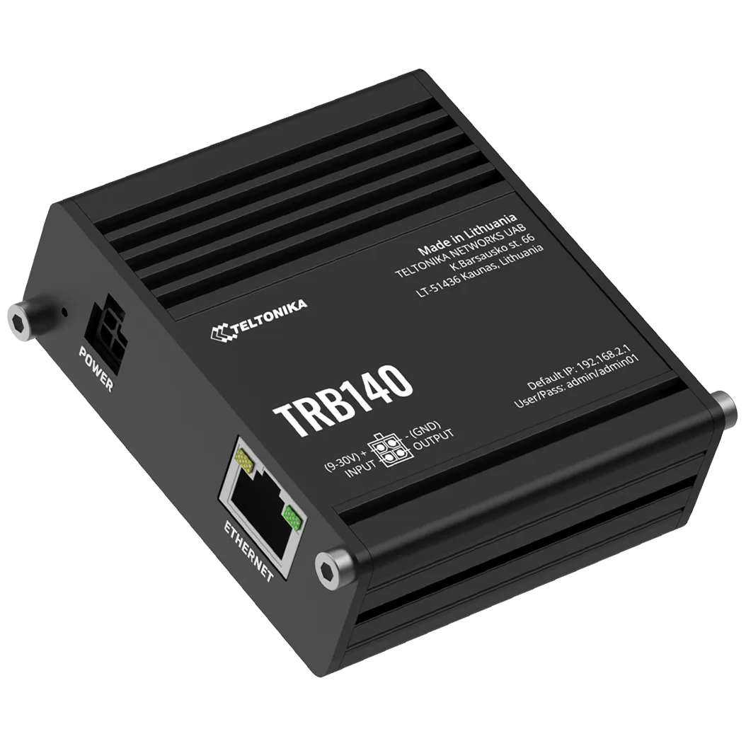
4G Router
An internet connection is essential for the system's operation. If no connection is available, Climkit can provide it via a 4G Router equipped with an active multi-operator SIM card.
Using the Climkit TRB140 4G Router offers several advantages:
- Simplified installation: the router is easily installed inside the electrical panel, directly on the DIN rail
- Complete delivery: supplied with its DIN rail support and its 24V DC power supply
- Ready to use: delivered preconfigured with an activated SIM card
- Economical 4G subscription: low-cost internet connection
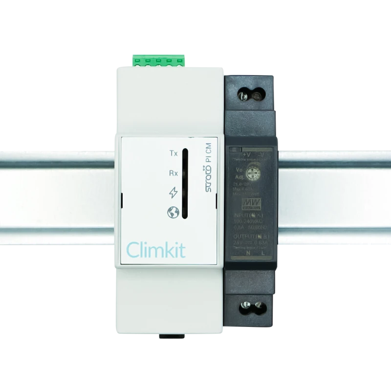
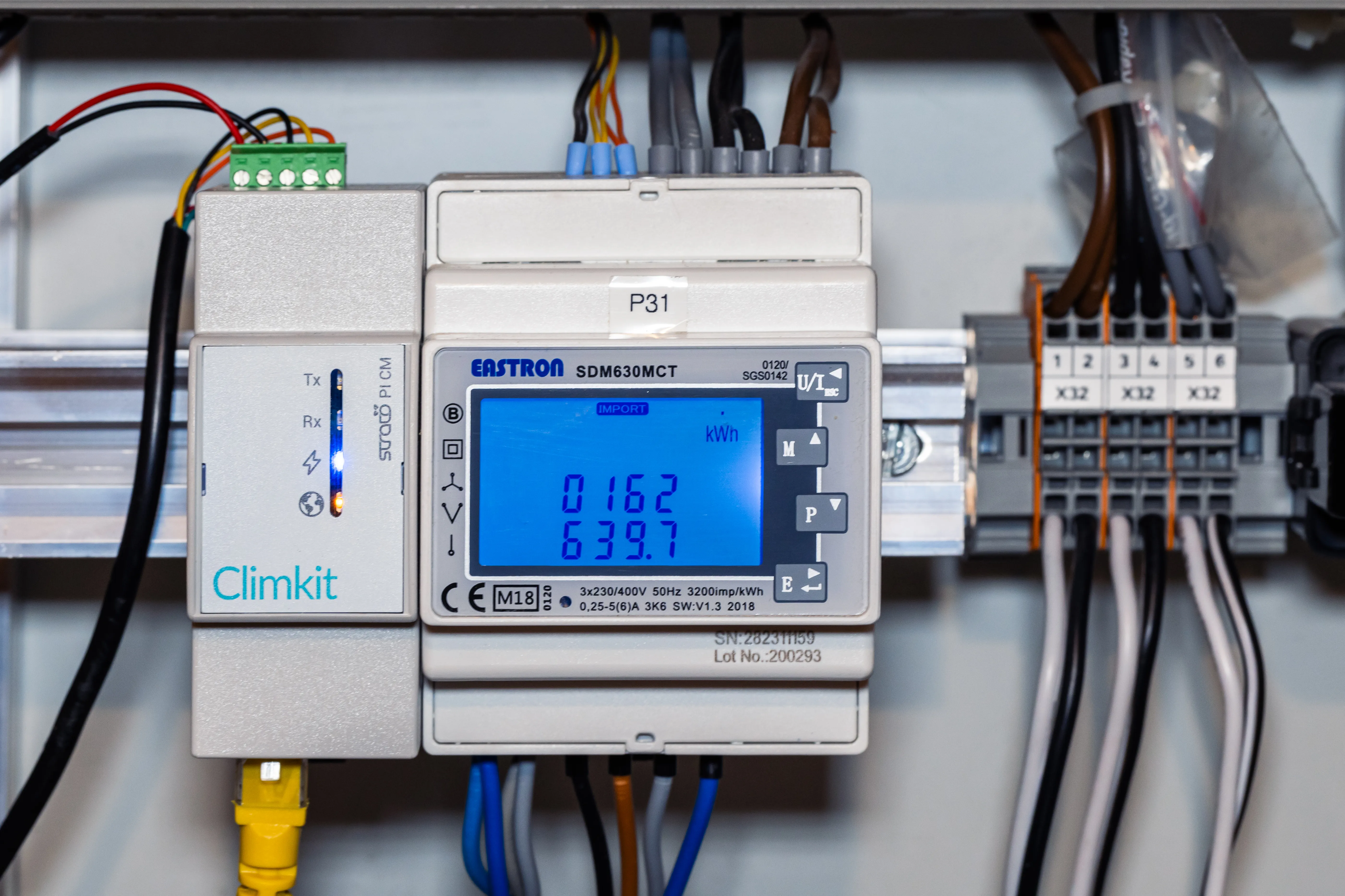
Climkit Gateway
The Climkit Gateway reads meters connected to its RS485 port via the Modbus protocol and transmits the readings to the Climkit platform via the internet.
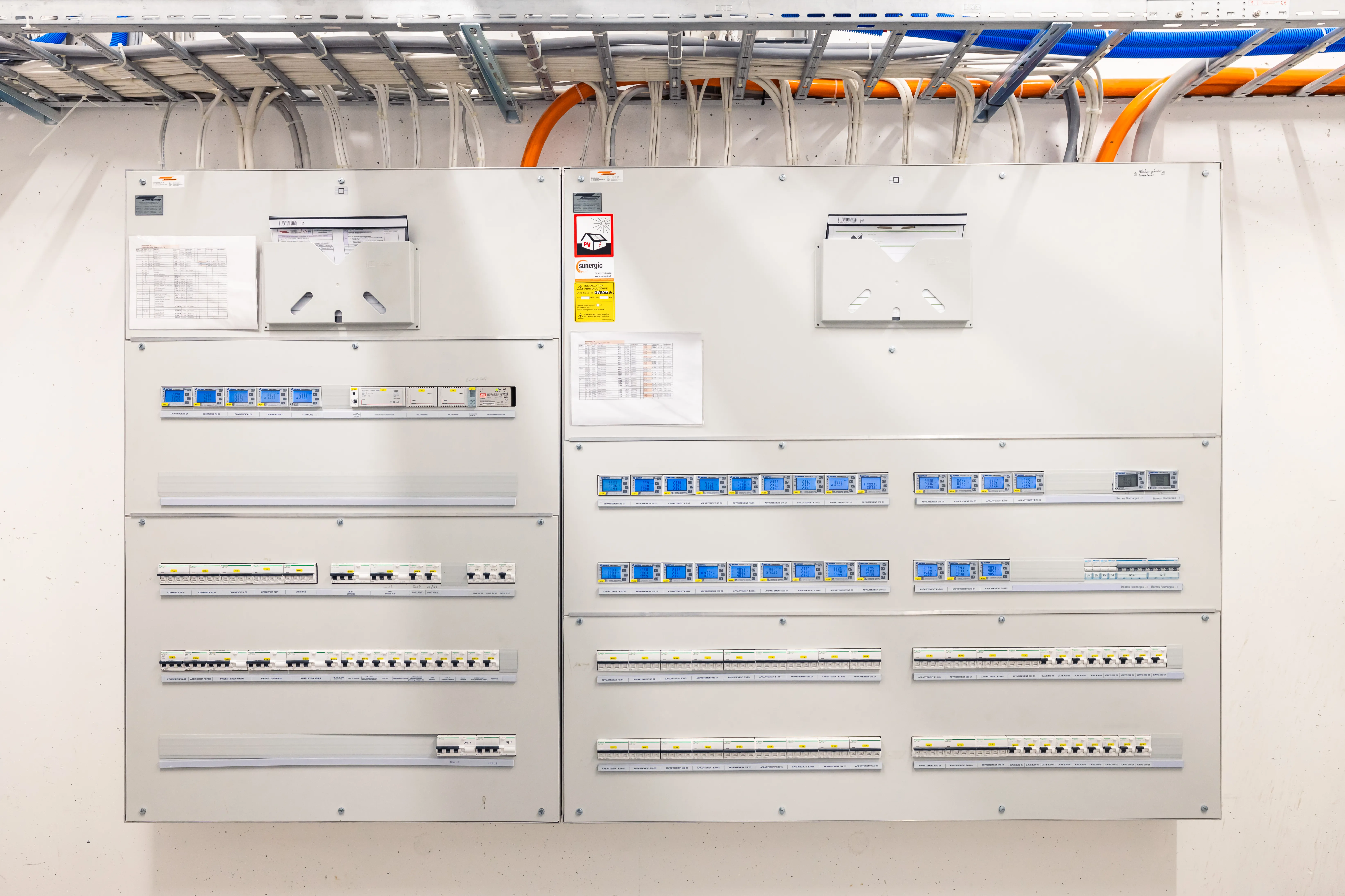
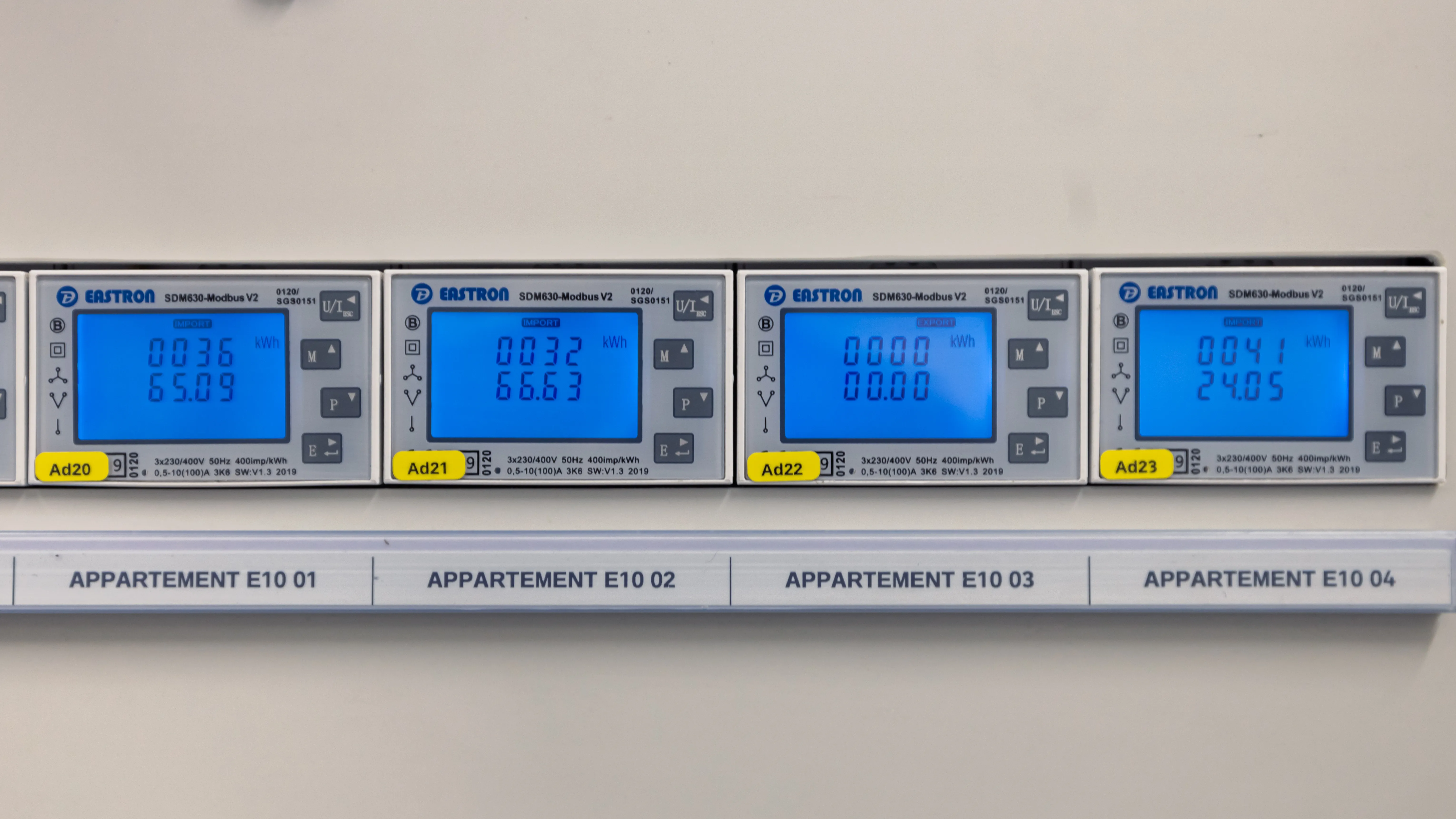
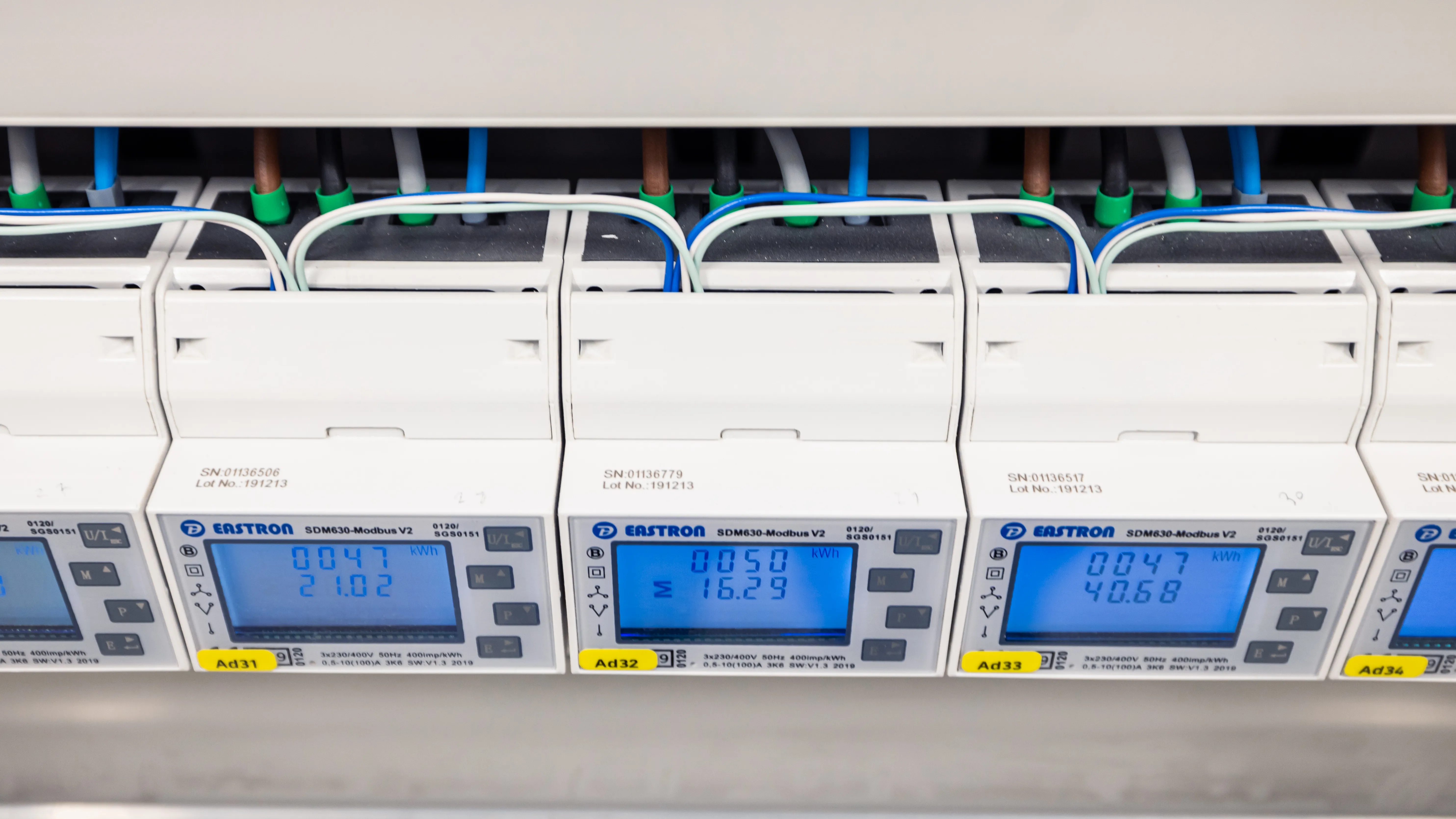
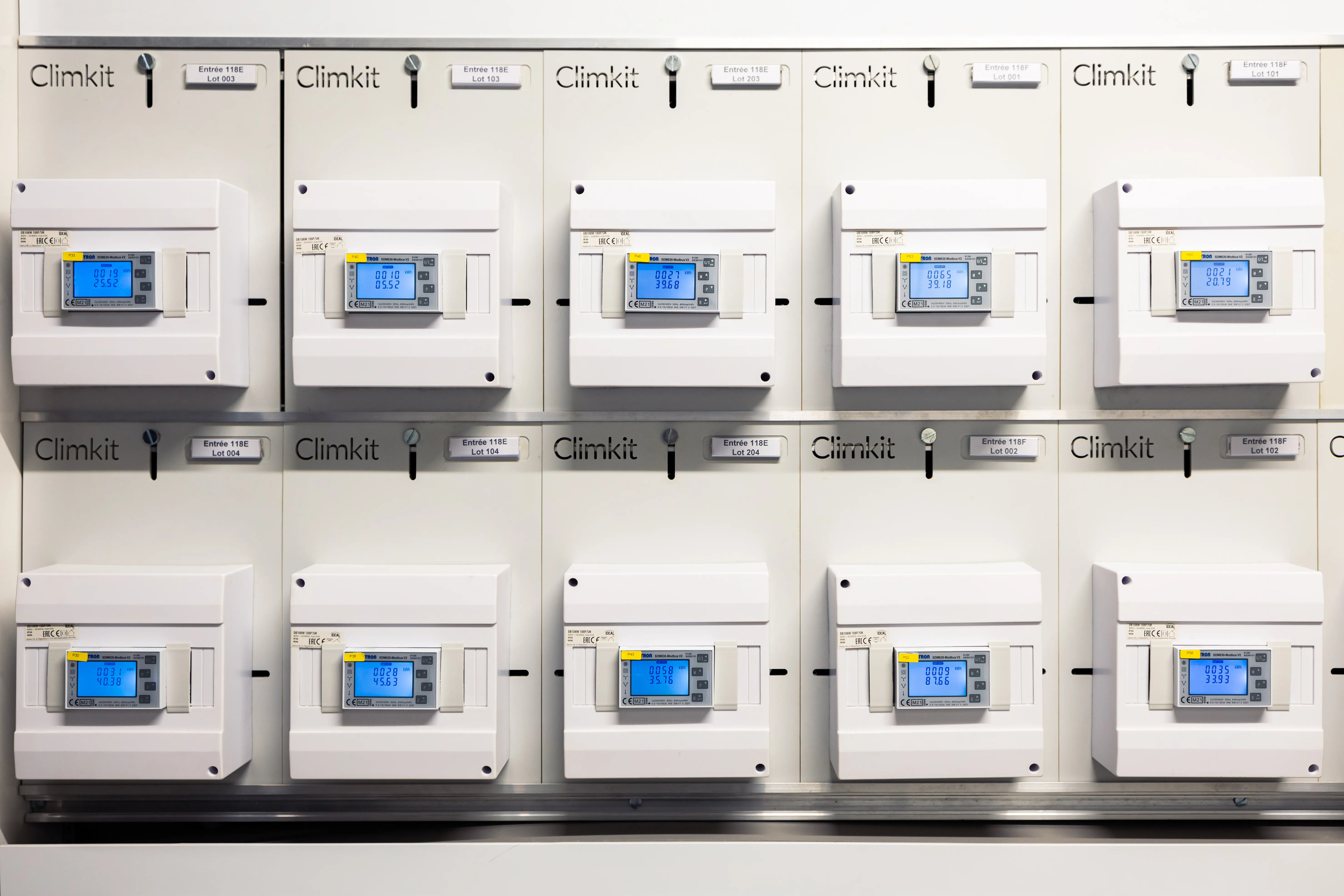
Electricity meters
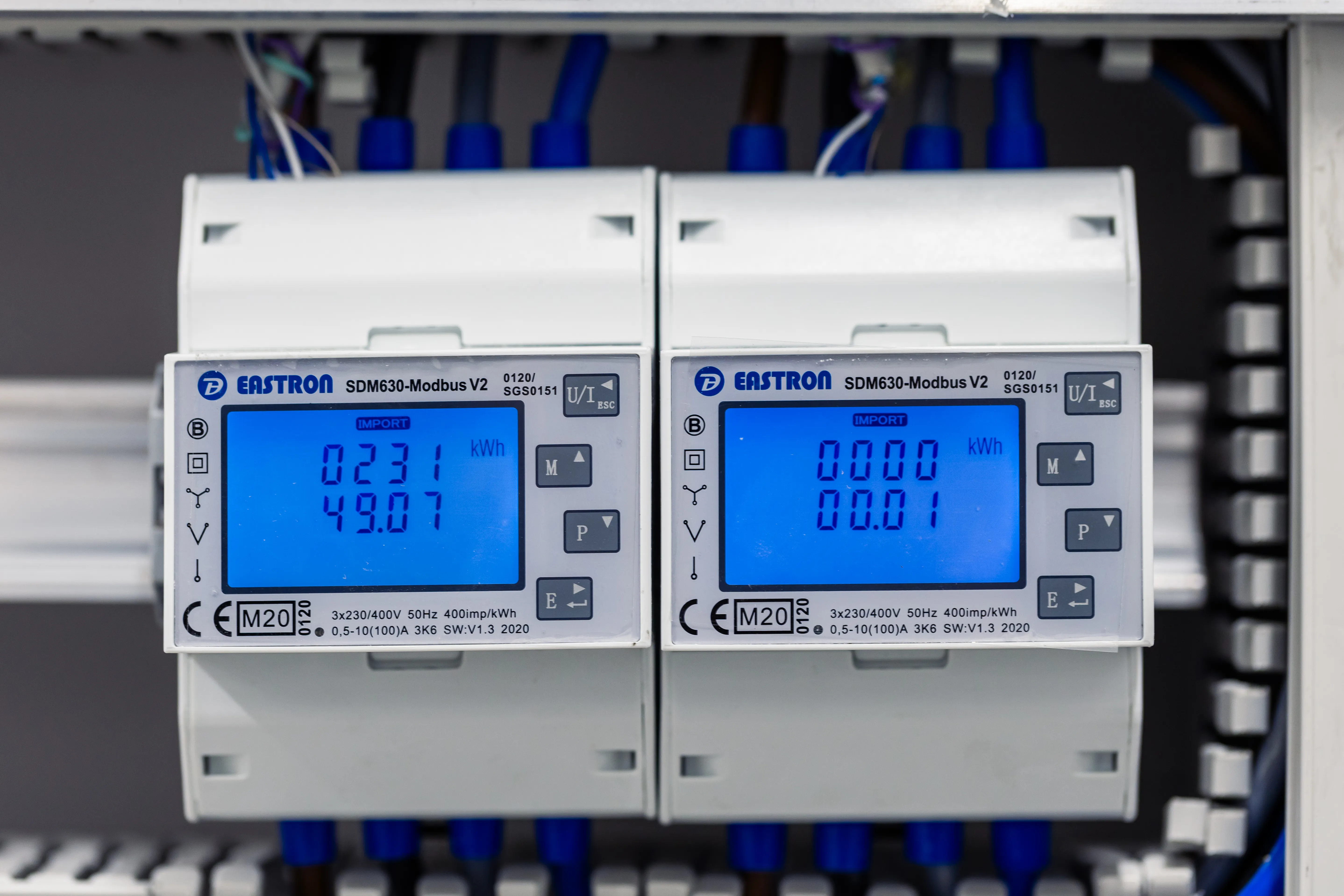
Electricity meters allow the measurement of consumption, production as well as electricity imported from and fed back to the grid.
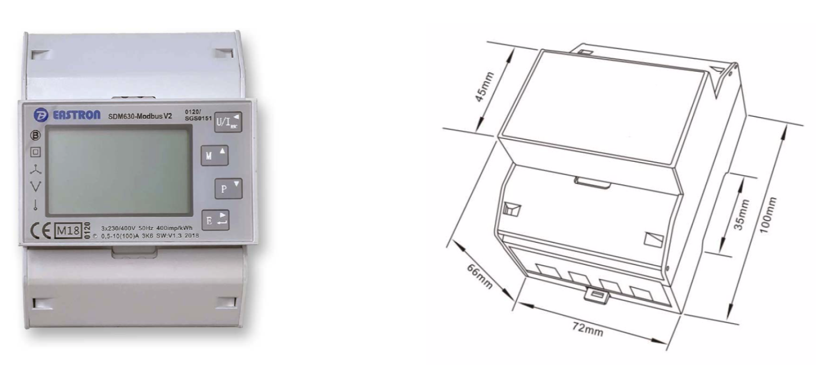
In the case of a connection below 80A, Climkit provides direct meters, meaning that the conductor wires pass directly through the meter.
The model generally provided is the Eastron SDM630Modbus meter. The meter is 4 DIN modules wide and is installed directly in the electrical panel on a DIN rail or in a suitable housing (see T-Box below).
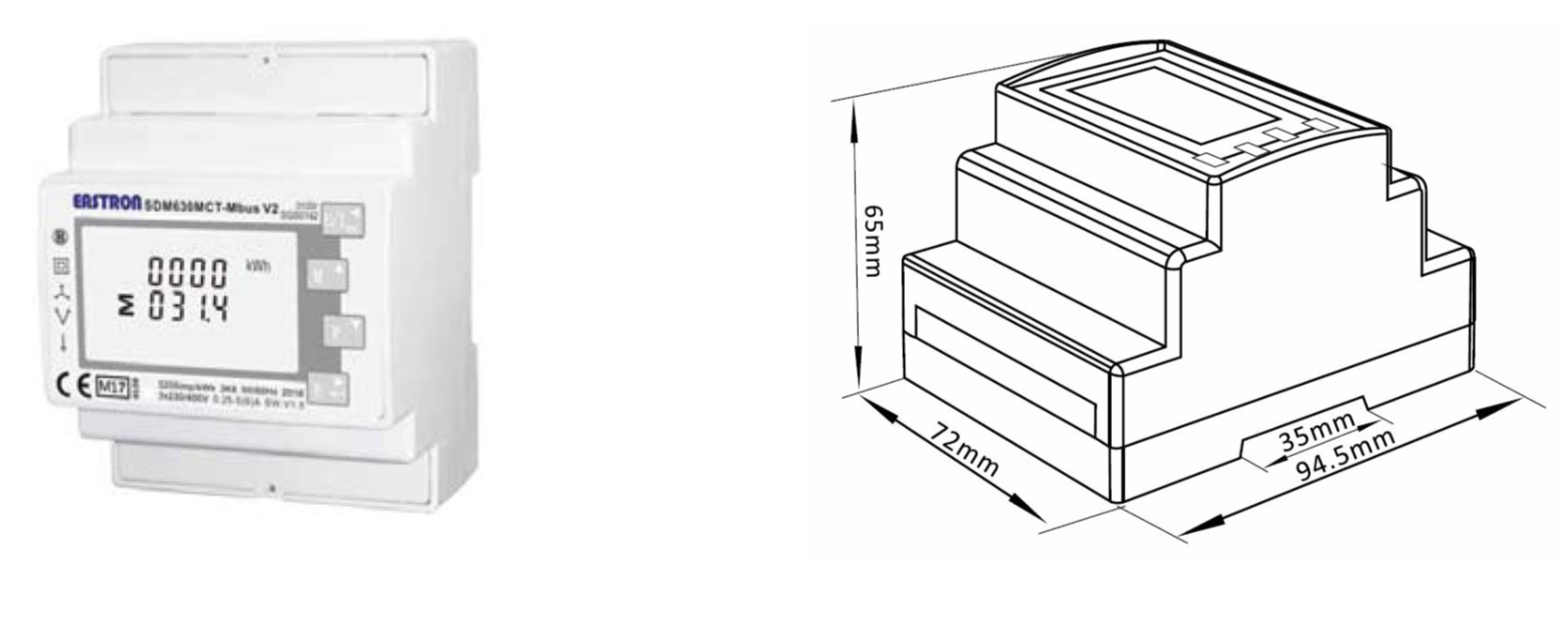
In the event that the connection intensity (amperage) exceeds 80A, Climkit provides indirect electricity meters, meaning that the conductor wires pass through current transformers (CT) which are themselves connected to the meter.
- The model generally provided is the Eastron SDM630MCT meter
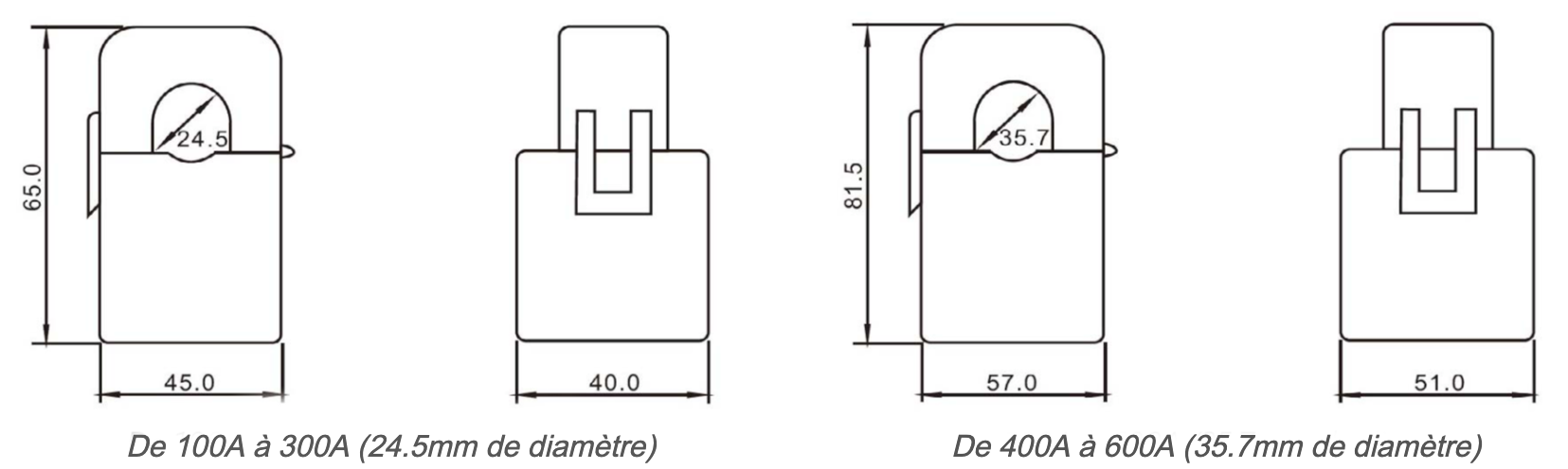
Current transformers (CT)
CTs are chosen according to the connection intensity and the diameter of the conductor on which the CT will clip around.
Climkit provides CTs ranging from 100 A to 2000 A.
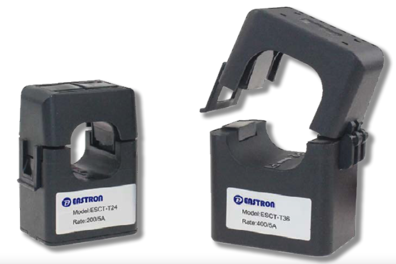
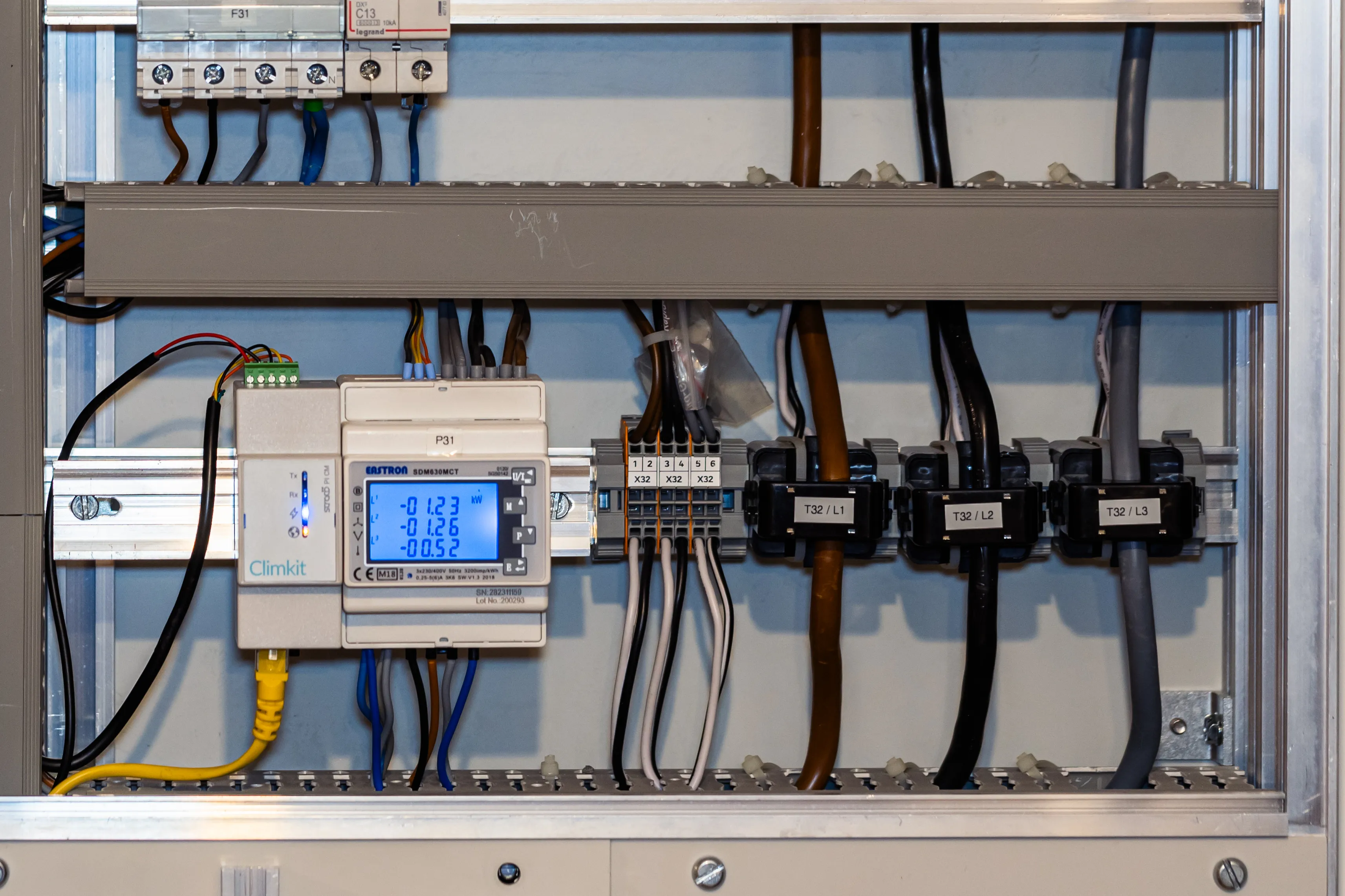
The CTs clip directly onto the cable or copper bar of each phase. Pay attention to the cable section relative to the CT diameter.
Other CTs can be ordered for specific cases with a larger diameter. To be specified at the time of order.
T-Box housing and meter plate
To facilitate the installation of meters on DSO meter locations, it is possible to order DIN rail housings with a mounting plate.
DIN rail housing on T mounting plate (H: 36cm, W: 21cm)
Option: Pre-wired input board
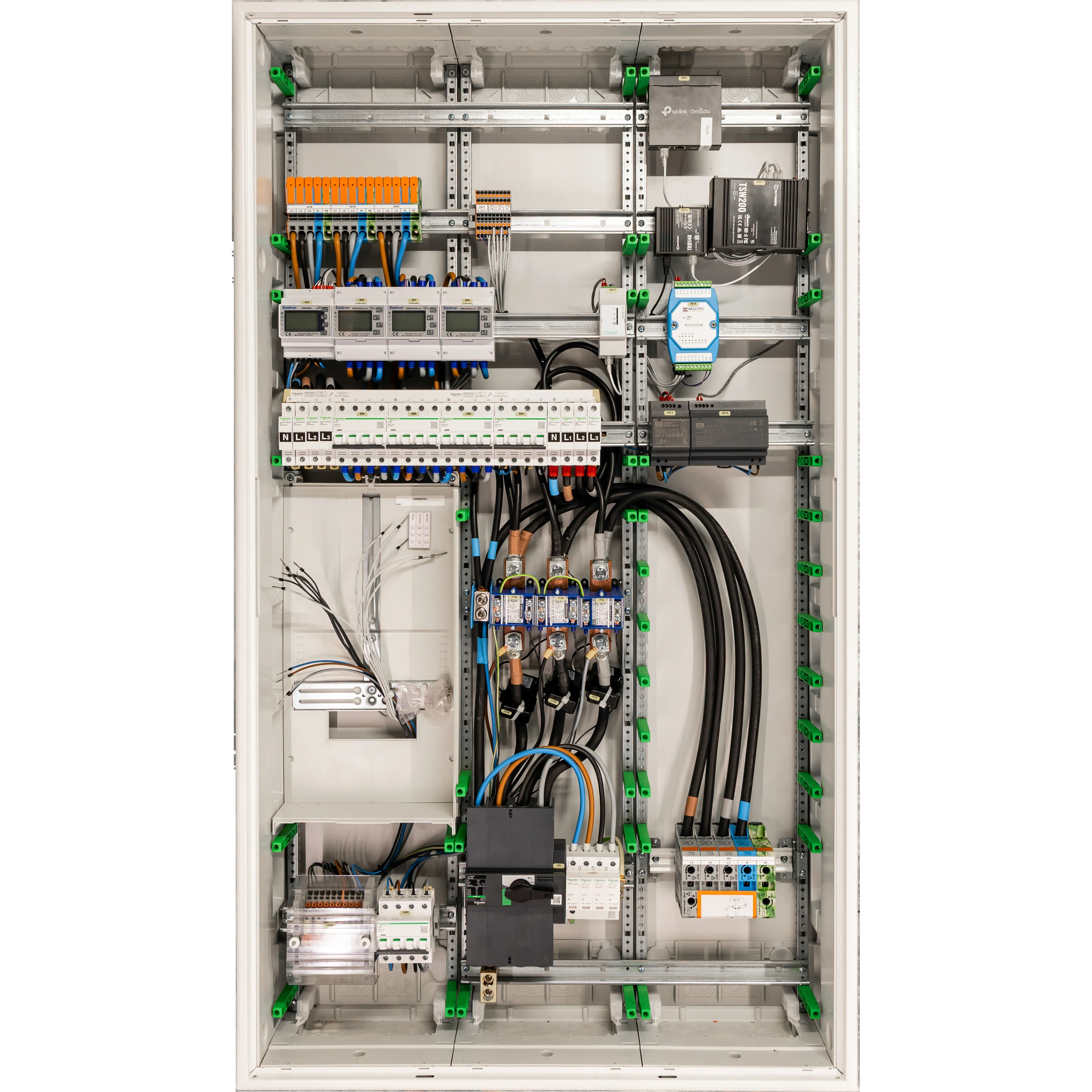
Climkit offers a pre-wired input board allowing all the elements necessary for an RCP (photovoltaic, battery and charging stations) to be grouped at the site's introduction point.
It integrates:
- the grid introduction (up to 160 A depending on the variant)
- the DSO meter location
- photovoltaic inverter outputs (≤ 30 kVA), AC battery and charging stations
- the general, PV, battery and charging station private meters
- the Climkit communication infrastructure (Gateway, multi-operator 4G Router, PoE Ethernet switch)
Ready to mount and developed by Climkit, it brings together the introduction and communication infrastructure necessary for integrating the solutions.
Assembled in Switzerland with Schneider Electric components, it is available in two variants:
Variant up to 80 A (direct metering)
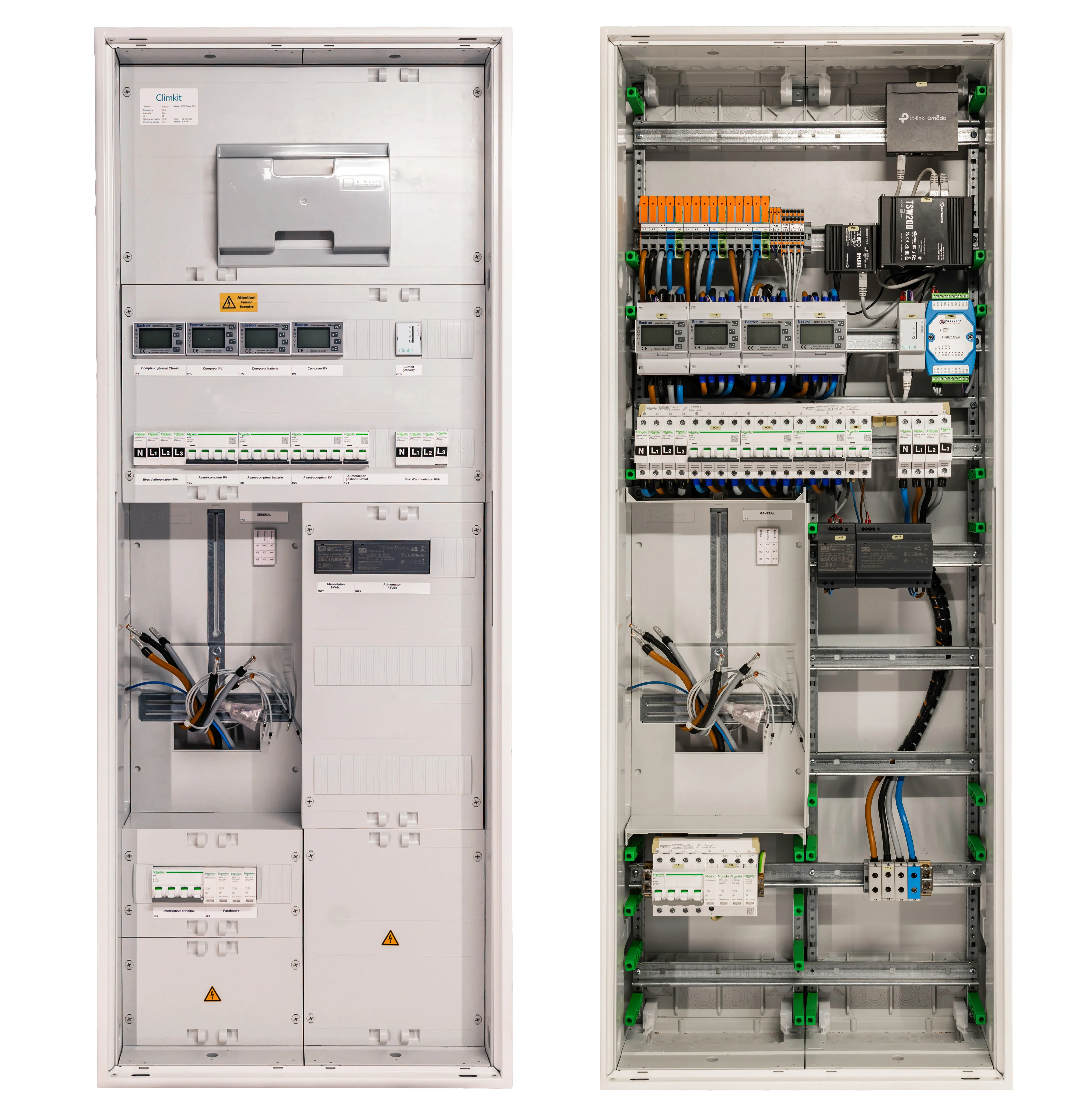
Variant up to 160 A (indirect metering with CT)
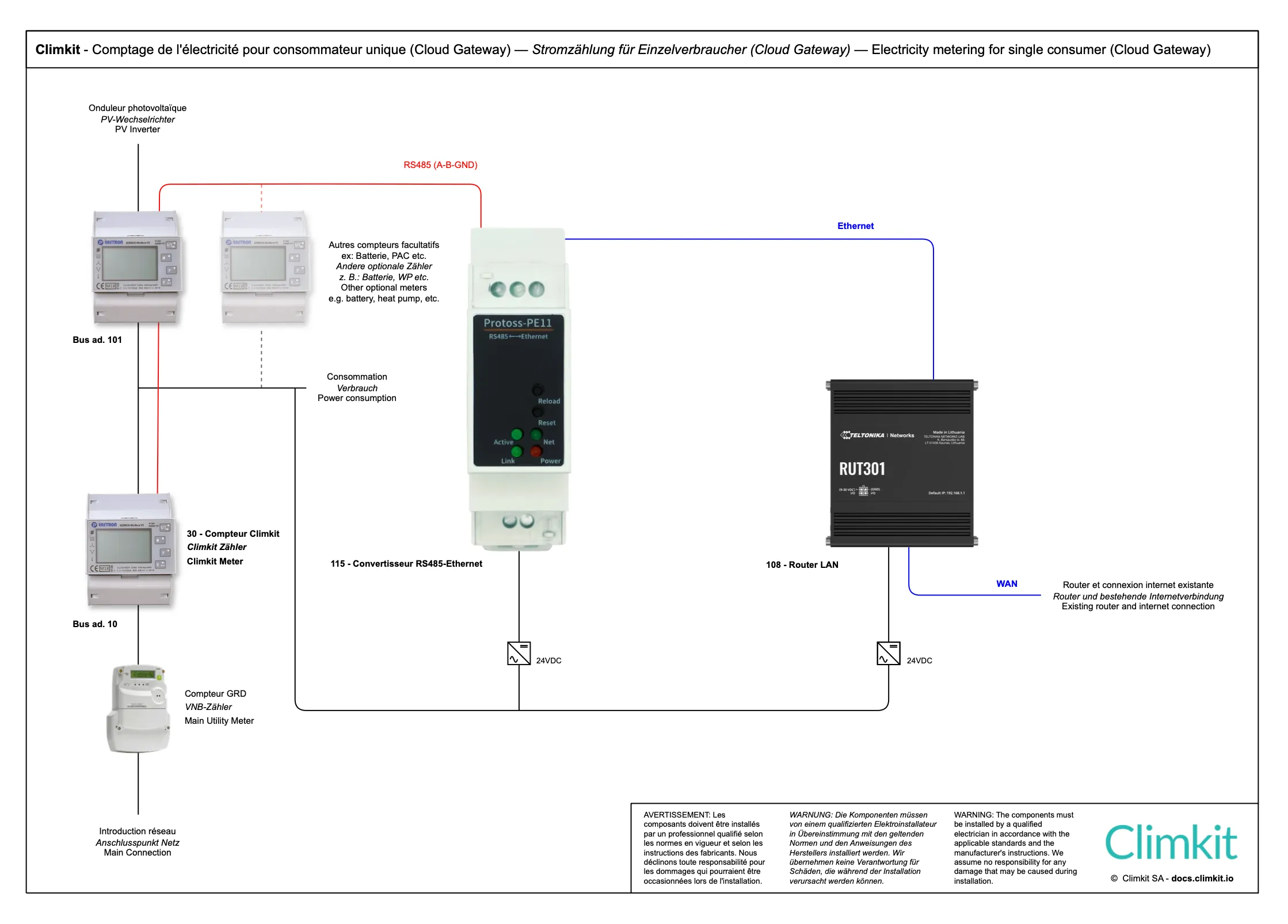
Variant with Cloud Gateway
Instead of using a Climkit Gateway, it is possible to opt for a virtual Gateway using the MQTT protocol, by combining a router (LAN or 4G) with an RS485-Ethernet converter.
Cloud Gateway diagram with 4G Router
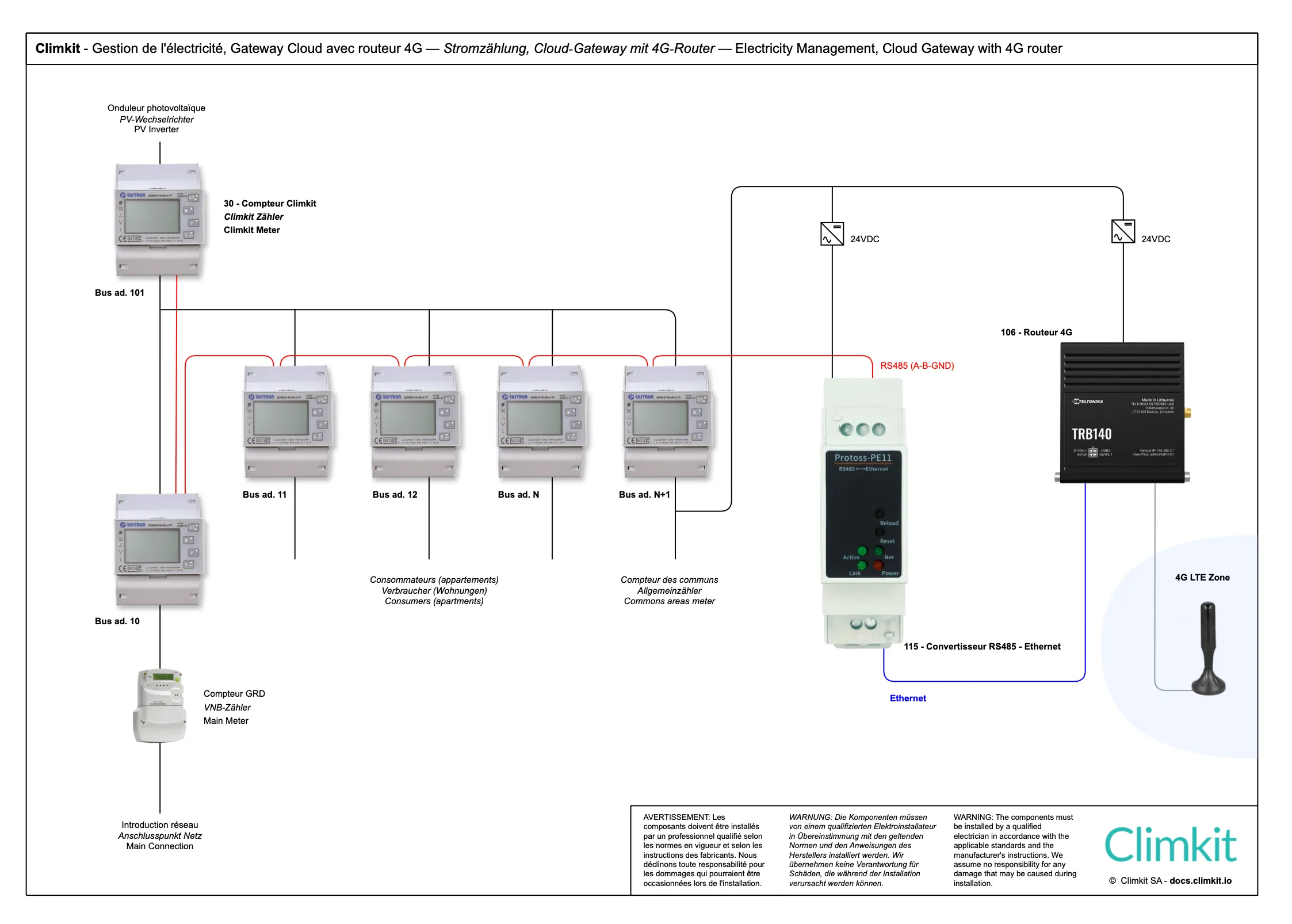
Diagram with LAN router

2. Connection variants
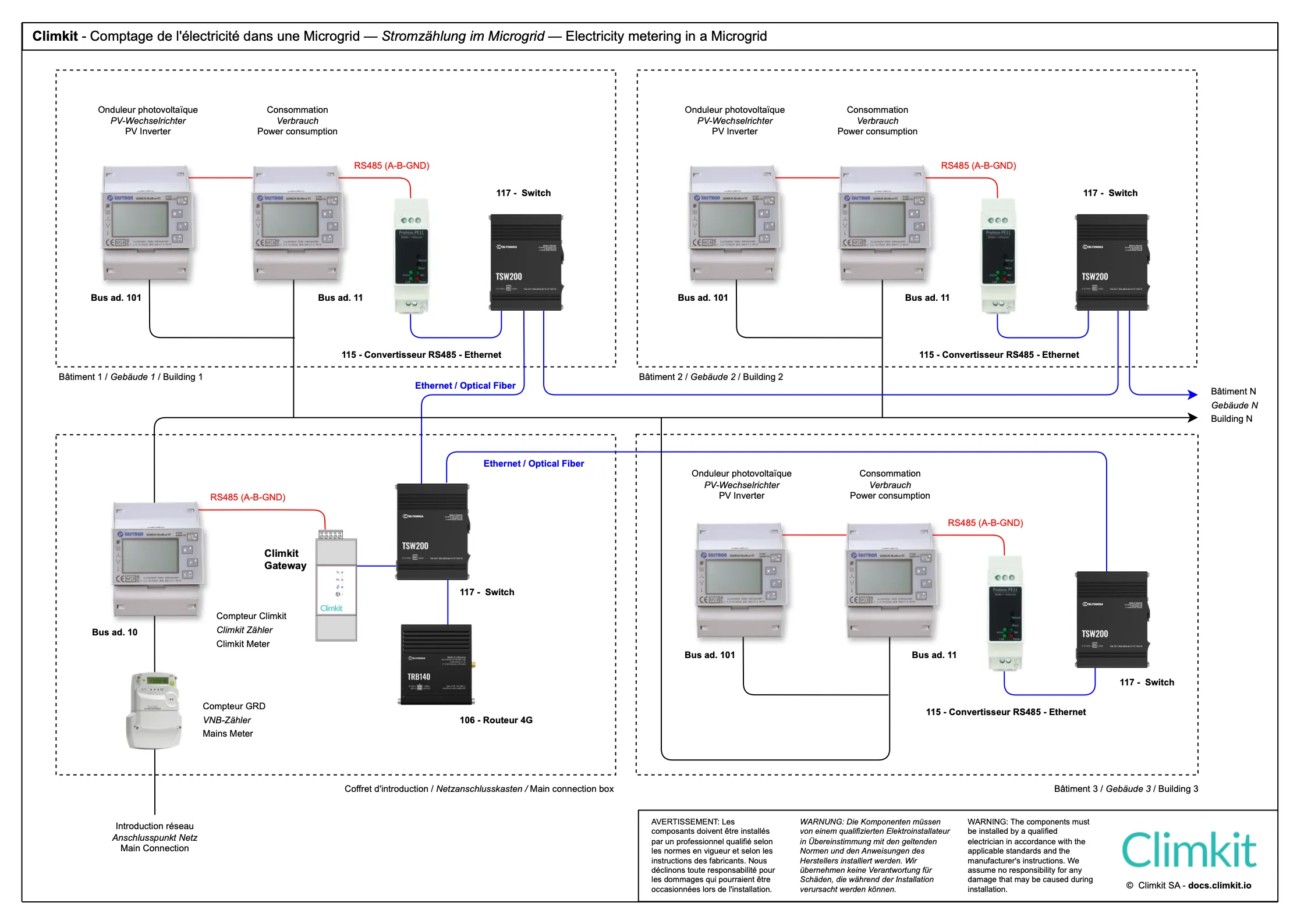
Microgrid diagram: Site consisting of several buildings
The Microgrid diagram consists of a community (RCP) with the following characteristics:
- A single point of introduction to the public network, equipped with a DSO input meter, generally located in a separate main low voltage switchboard room or in one of the Site's buildings.
- Multiple buildings connected to this same introduction point.
- Multiple consumers (apartments, offices, common areas, etc.), each connected to an individual meter.
This scheme applies particularly when private meters are distributed across different points of the site. Several variants are then possible for connecting and reading the meters:
- Installation of a bus between buildings, passing through each meter to the central Climkit Gateway.
- Installation of a Climkit Gateway in each building, each connected to the Internet for data transmission.
- Recommended: Interconnect all buildings via a local IP network (RJ45 cabling or fiber optic). Each meter installation is connected to an RS485-Ethernet converter, itself connected to the site's LAN. This architecture allows for efficient data centralization while ensuring infrastructure flexibility. (See diagram below.)
This last variant is recommended because it offers several advantages:
- Increased reliability: It avoids connection problems related to the physical bus between buildings, the diagnosis and troubleshooting of which can be complex.
- Equipment savings: It allows for the installation of only one Gateway and one router for the entire site, thus simplifying the architecture and reducing costs.
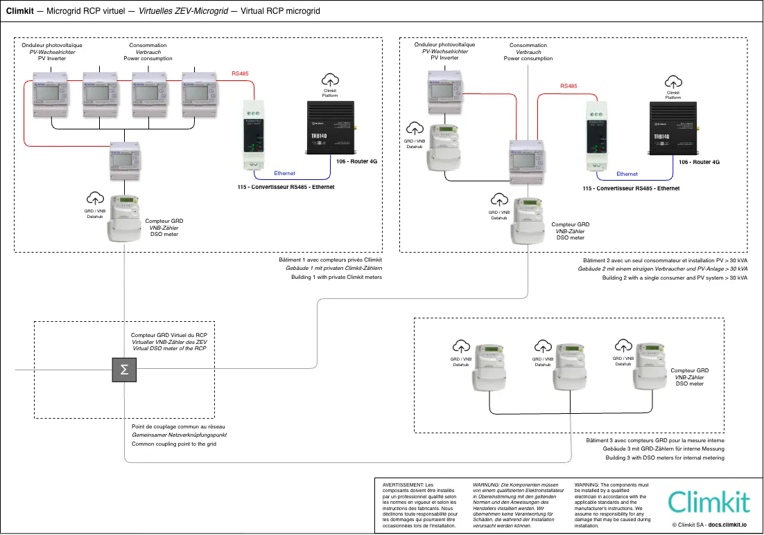
Microgrid diagram with virtual RCP with several introductions
The Microgrid diagram with virtual RCP consists of:
- Several points of introduction to the public network, each with its DSO meter
- Several interconnected buildings
- Several consumers (apartments, offices, common areas, etc.) equipped with either a private meter or a DSO meter
- Several photovoltaic installations measured by a private meter or a DSO meter
Operating principle:
The produced electricity is shared between buildings. DSO meters are virtually grouped to establish a single invoice for grid withdrawal.
Private meters are read directly by the Climkit Gateway, while the DSO transmits data from its meters to Climkit. All information is centralized on the Climkit platform.
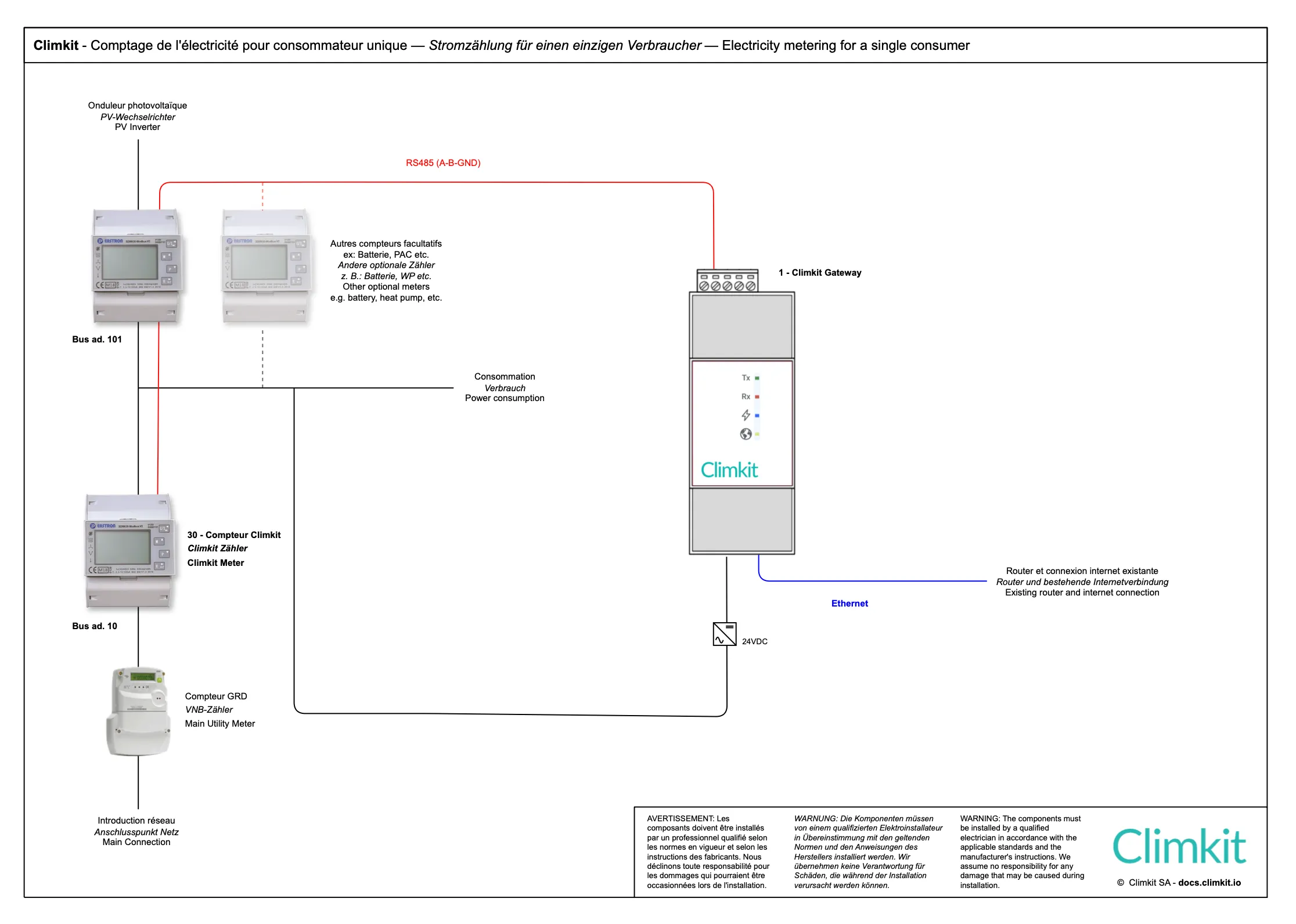
Single consumer diagram
This scheme applies to Sites including:
- A single point of introduction to the public network
- A single consumer
- A single photovoltaic installation
Application example: A single-family house or a commercial building equipped with a photovoltaic installation.
At least two meters are installed: an input meter in series with the DSO meter and a photovoltaic production meter.
Consumption does not need to be measured directly: it is deduced by calculation from the values of the other two meters (Consumption = Production + Withdrawal or - Injection).
Cloud Gateway variant with LAN (or 4G) router
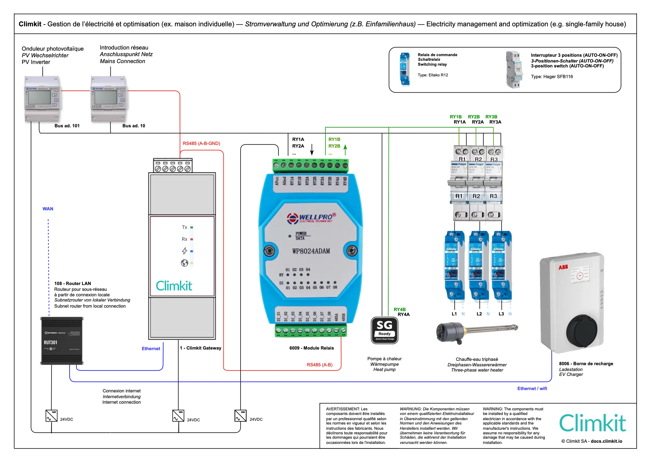
3. Self-consumption optimization
Climkit's optimization system increases the self-consumption rate of a photovoltaic installation by controlling certain devices based on solar energy production.
The surplus fed back to the electrical grid is thus limited, and autonomy is gained, for example, by producing hot water with solar energy.
Devices (water heaters, heat pumps, radiators, pool pumps, etc.) are controlled via a relay. It is also possible to control certain electric vehicle charging stations (via Wifi or Ethernet).
Climkit Offer
Here are the additional products to enable self-consumption optimization:
- Equipment:
- Relay I/O Module
- Software features:
- Optimization of self-consumption
- Setup service:
- Technical coordination and configuration
Details of equipment used
Relay I/O Module
The WP8024 I/O Module provided by Climkit has 4 relays.
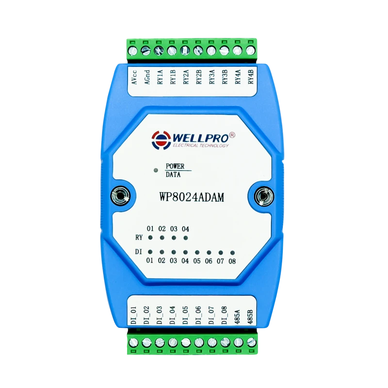
It is delivered with a 24V DC DIN rail power supply and connects to the Climkit Gateway via RS485-Modbus (same as electricity meters).
Potential-free contacts (e.g., SG-ready from the heat pump) can be connected directly to a module relay.
In the case of a water heater, the module's relays control control relays (contactor) which themselves switch on the water heater.
A three-phase heating element can be connected with an independent relay per phase to allow switching by stages and maximize self-consumption even in cases of low photovoltaic production.
If 4 relays are not enough, it is possible to connect several modules to the Climkit Gateway.
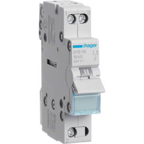
It is recommended to install a 3-position switch between the relay module and the device to be controlled in order to be able to switch the latter on manually.
Positions:
- Up (I): Automatic controlled by the relay module and the optimization system
- Middle (0): Forced stop
- Down (II): Forced run
Standard model: Hager SFB116
4. Battery installation
In the case of an installation with an AC-type battery (equipped with its own charger-inverter), it is essential to connect this system to a specific Climkit battery meter and to configure the latter in "Battery" mode on the platform.