Table of Contents
Plan the connection of the Climkit Gateway and network connectivity

This article describes the installation planning. For on-site implementation and equipment configuration on the Climkit platform, refer to the links at the end of the article.
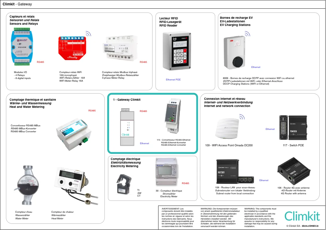
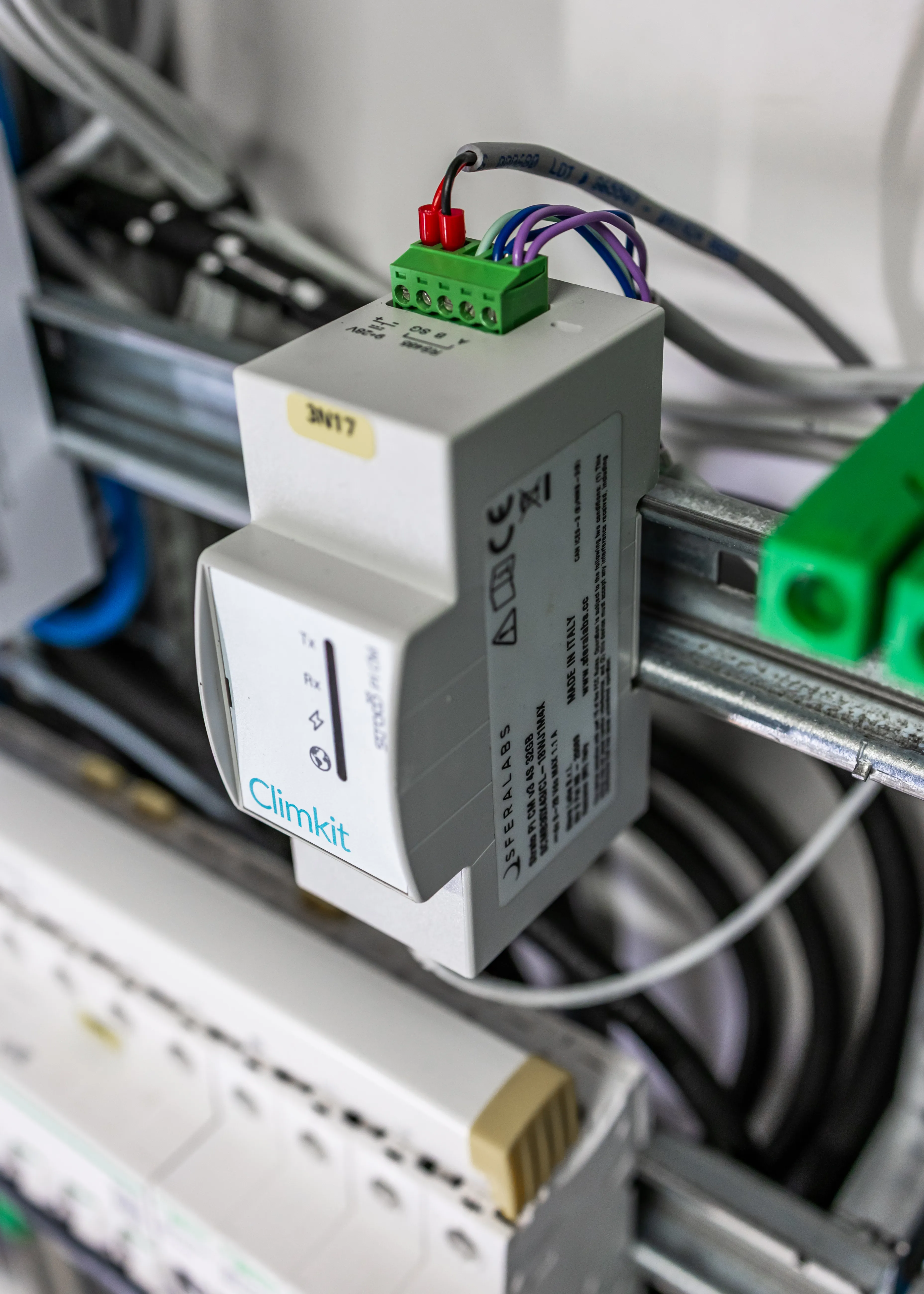
1. The Climkit Gateway
The Climkit Gateway is the communication gateway that centralizes and manages all the equipment for Climkit solutions. It allows for the collection and transmission of data from connected devices (meters, charging stations, RFID readers, etc.) to the Climkit online platform.
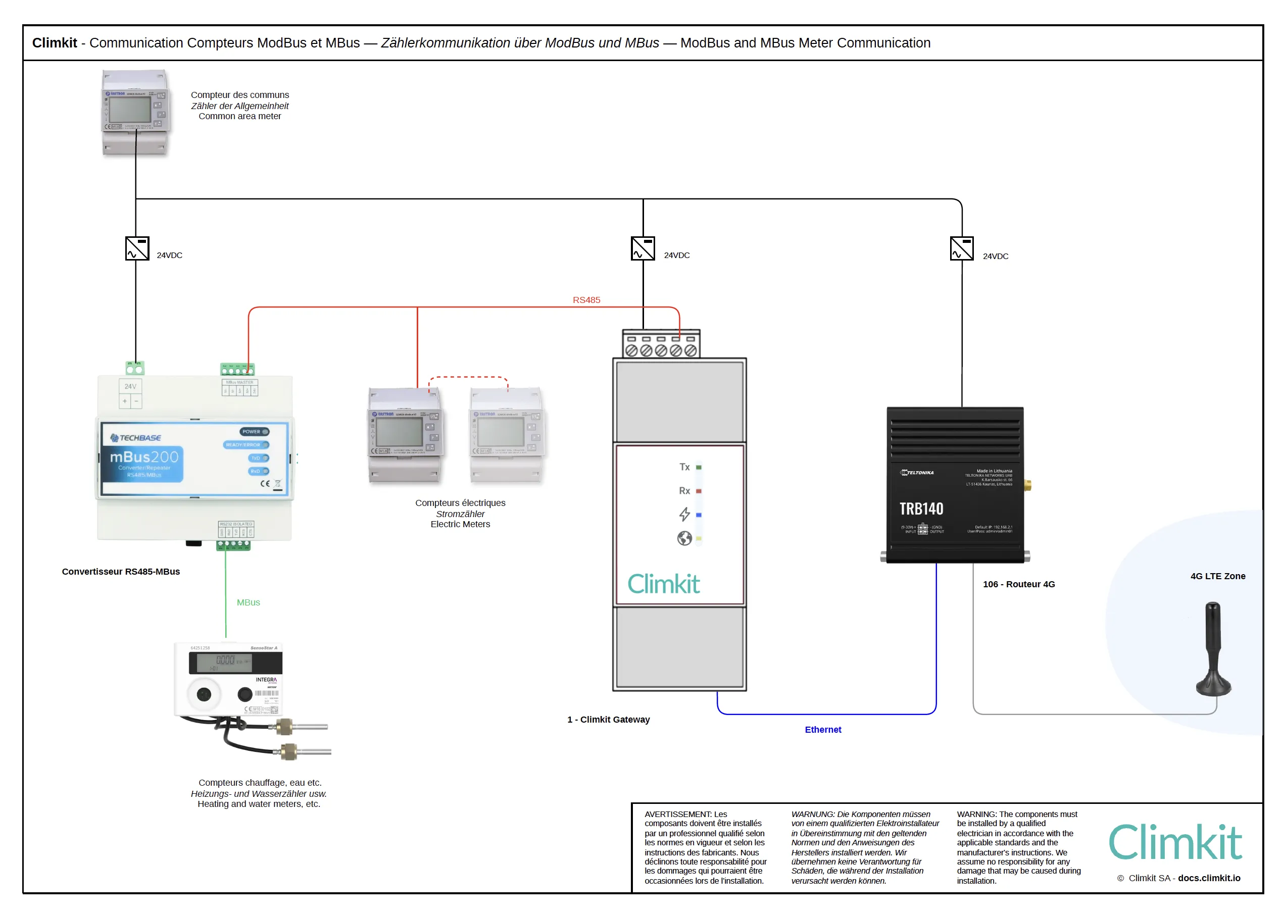
The Gateway communicates with the equipment via RS485 serial networks and TCP/IP networks, using standard and open (non-proprietary) communication protocols, notably Modbus, M-Bus, and OCPP.
The main equipment that connects to and is managed by the Climkit Gateway are:
- Electricity meters
- Electric vehicle charging stations
- RFID readers
- Control relays
- Sensors
- Storage Battery
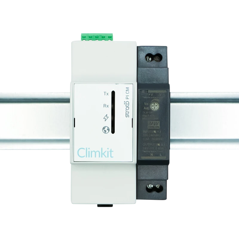
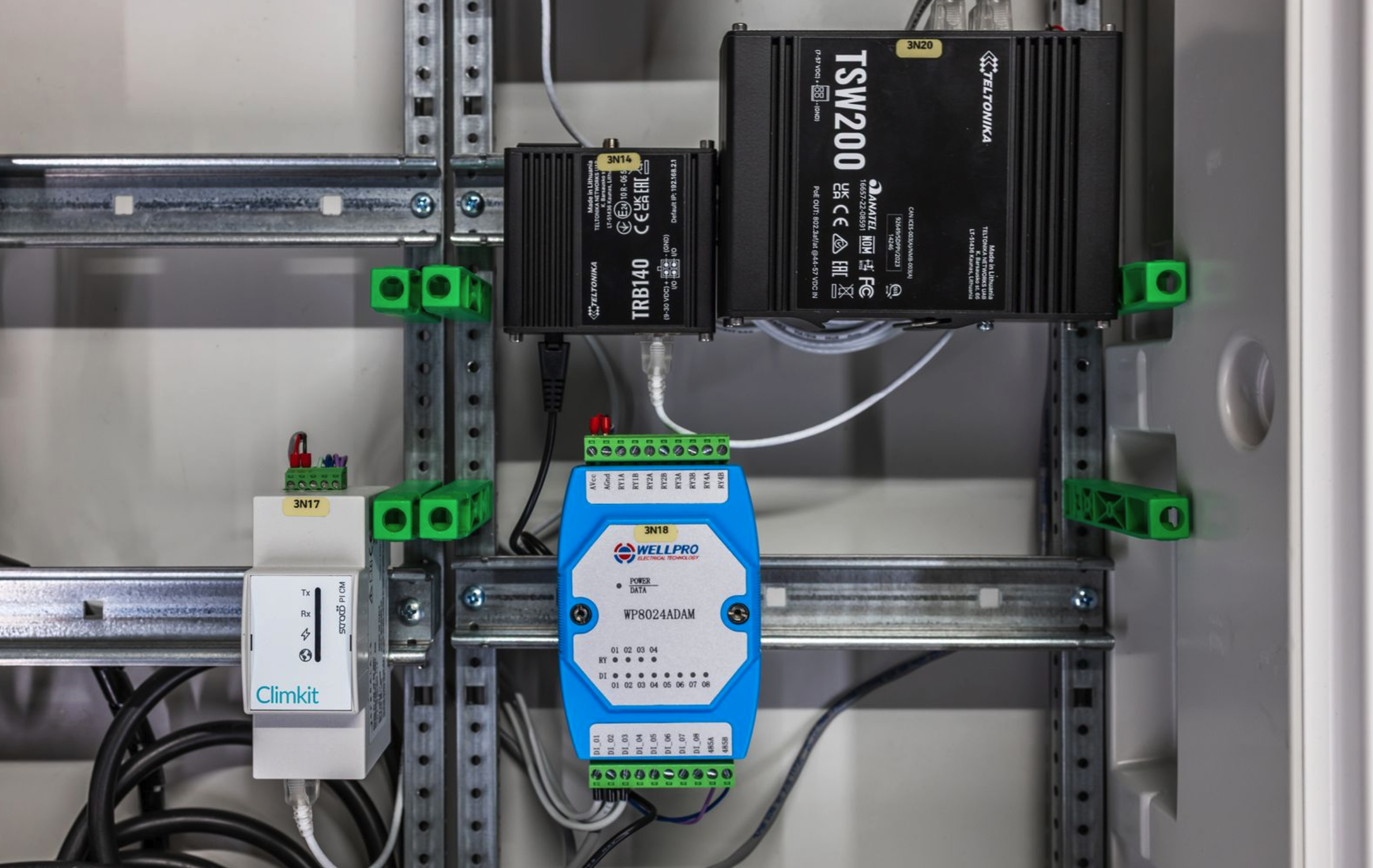
Installation in the electrical cabinet
The Gateway is supplied with its 24V DC power supply on a DIN rail.
It is connected to the network via the RJ45 Ethernet port.
Gateway width: 2 DIN modules.
It is strongly recommended to install a dedicated circuit breaker for Climkit communication devices. This should be clearly labeled. In the example below, the circuit breaker is associated with the Climkit Gateway and the MBus60 converter.
Connection to meters
The RS485 port allows for direct connection of RS485-Modbus electricity meters.
2. Other communication equipment
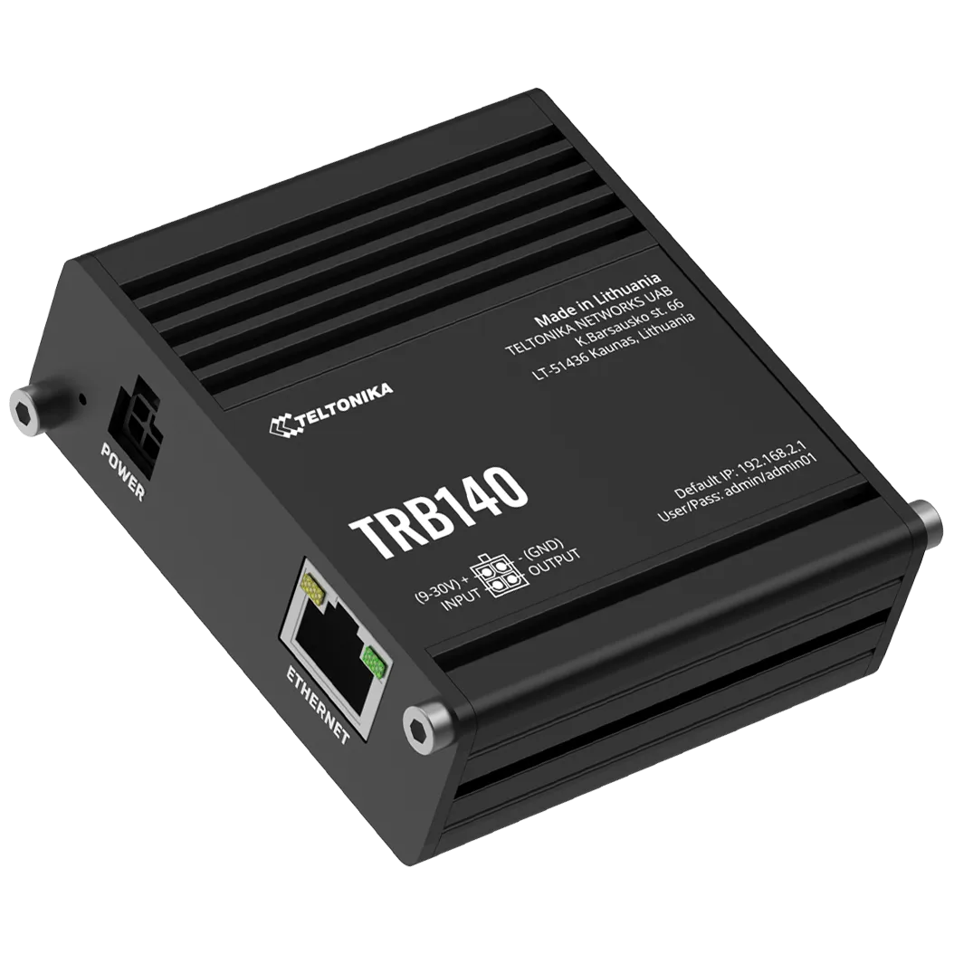
4G Router
The 4G Router is necessary when no internet connection is available in the building. It allows communication between the devices and the Climkit online portal via an inexpensive 4G subscription.
The router is supplied with a DIN rail mount and its 24V DC power supply, a 3m remote antenna, and an activated multi-operator SIM card.
The device used is a Teltonika TRB140 (or equivalent).
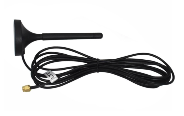
If the 4G signal is too weak or absent, order an antenna extension cable (5m or 10m) or move the router to an area with signal. It is not recommended to extend the antenna by more than 20m.
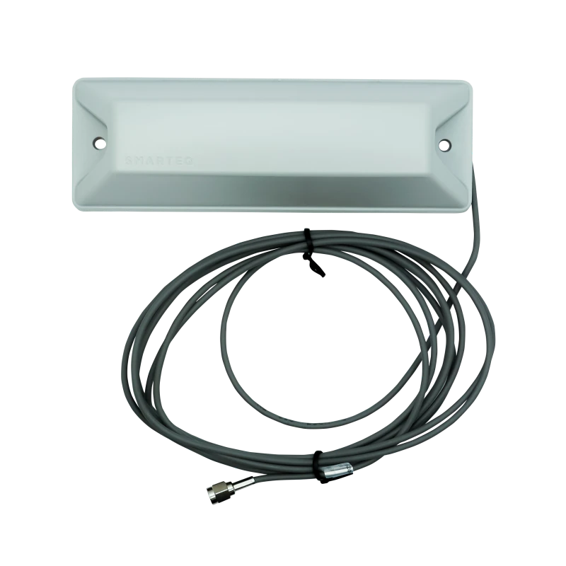
If necessary, an IP65 outdoor antenna is provided for installation on the facade or in a light well.
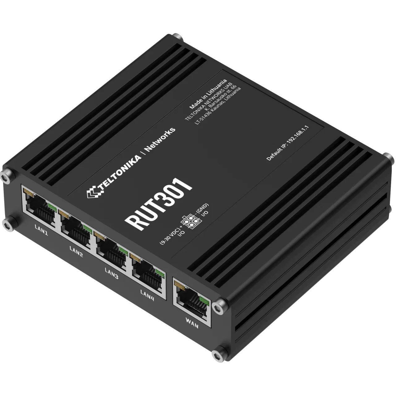
LAN Router
In cases where a local internet connection is available from another router, it is recommended to create a sub-network with a standard router to which all devices are connected (Climkit Gateway, charging stations, etc.). This ensures independence from the main router for configuration.
The device used is a Teltonika RUT301 with 4 LAN ports + 1 WAN, delivered with DIN rail support and its 24V DC DIN rail power supply.
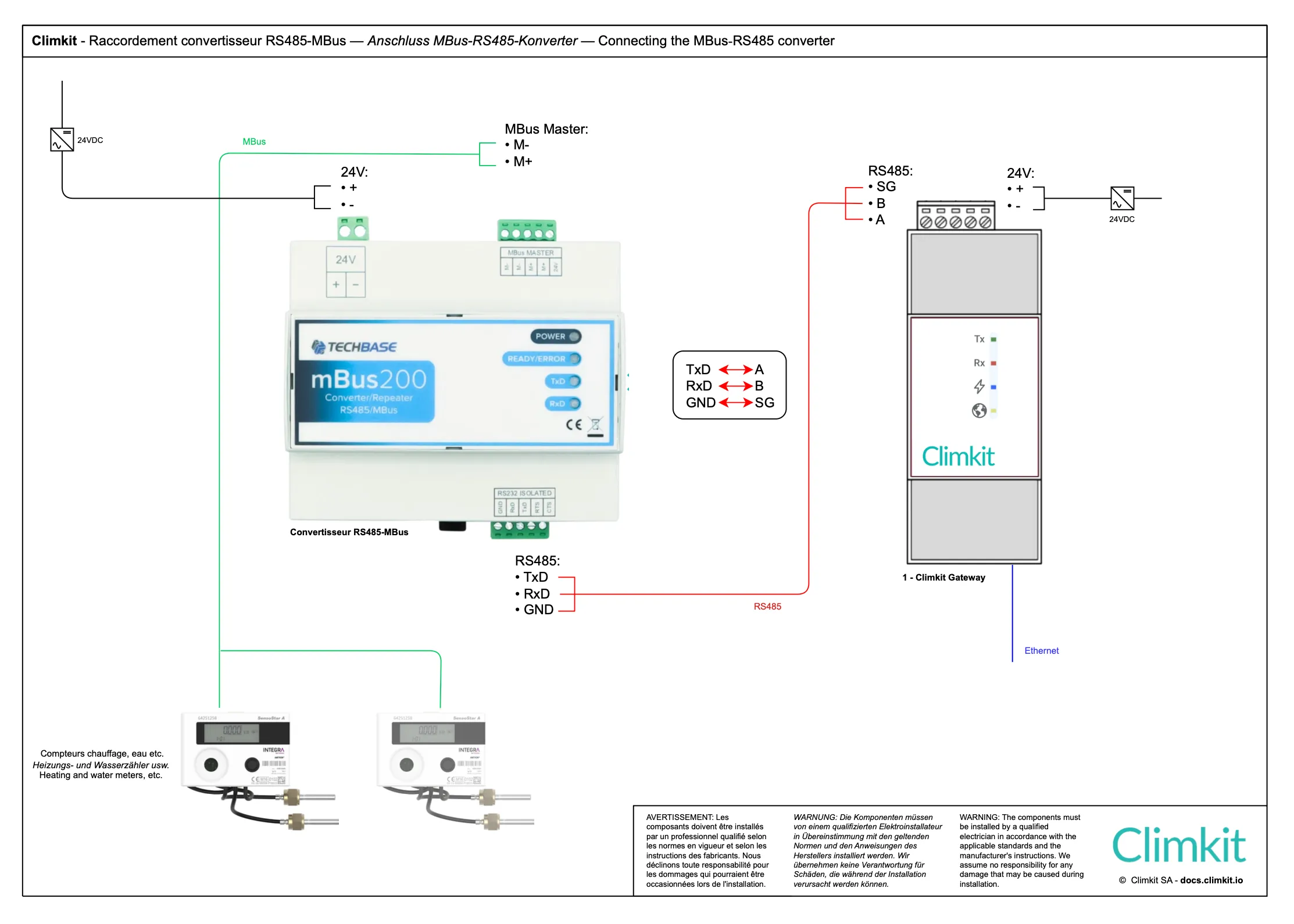
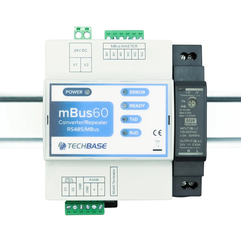
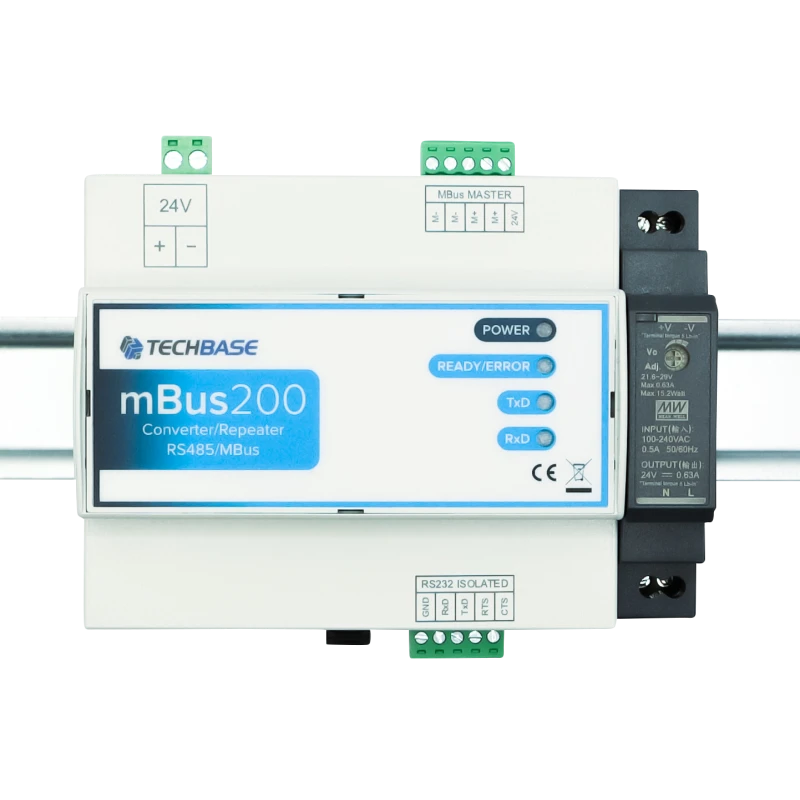
MBus-RS485 Converter
The M-Bus/RS485 converter allows for the connection of M-Bus meters (usually heat and water) to the Climkit Gateway.
Two models are available depending on the number of meters to be connected:
- M-Bus60: up to 60 meters - width 4 DIN modules
- M-Bus200: up to 200 meters - width 8 DIN modules
It is possible to connect several converters to the same Gateway to expand the system capacity.
Each converter is delivered with its 24V DC DIN rail power supply.
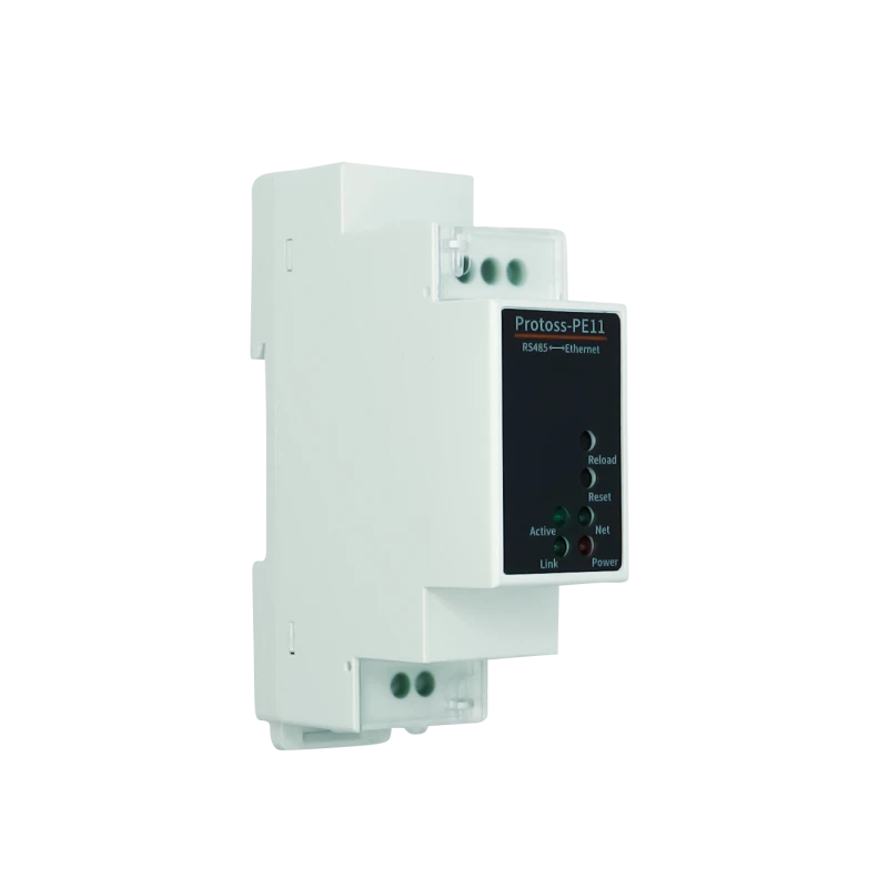
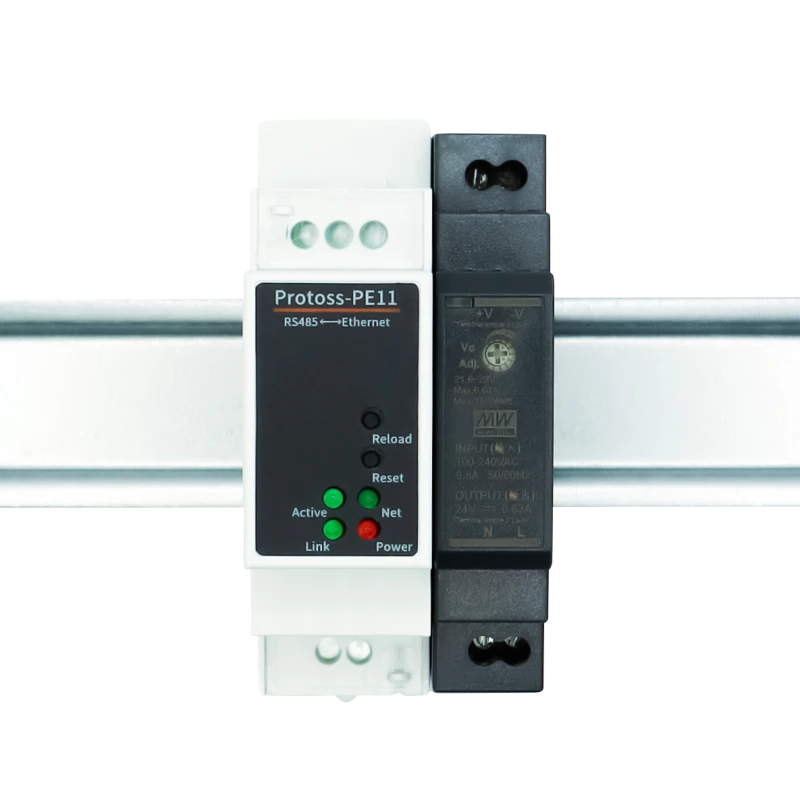
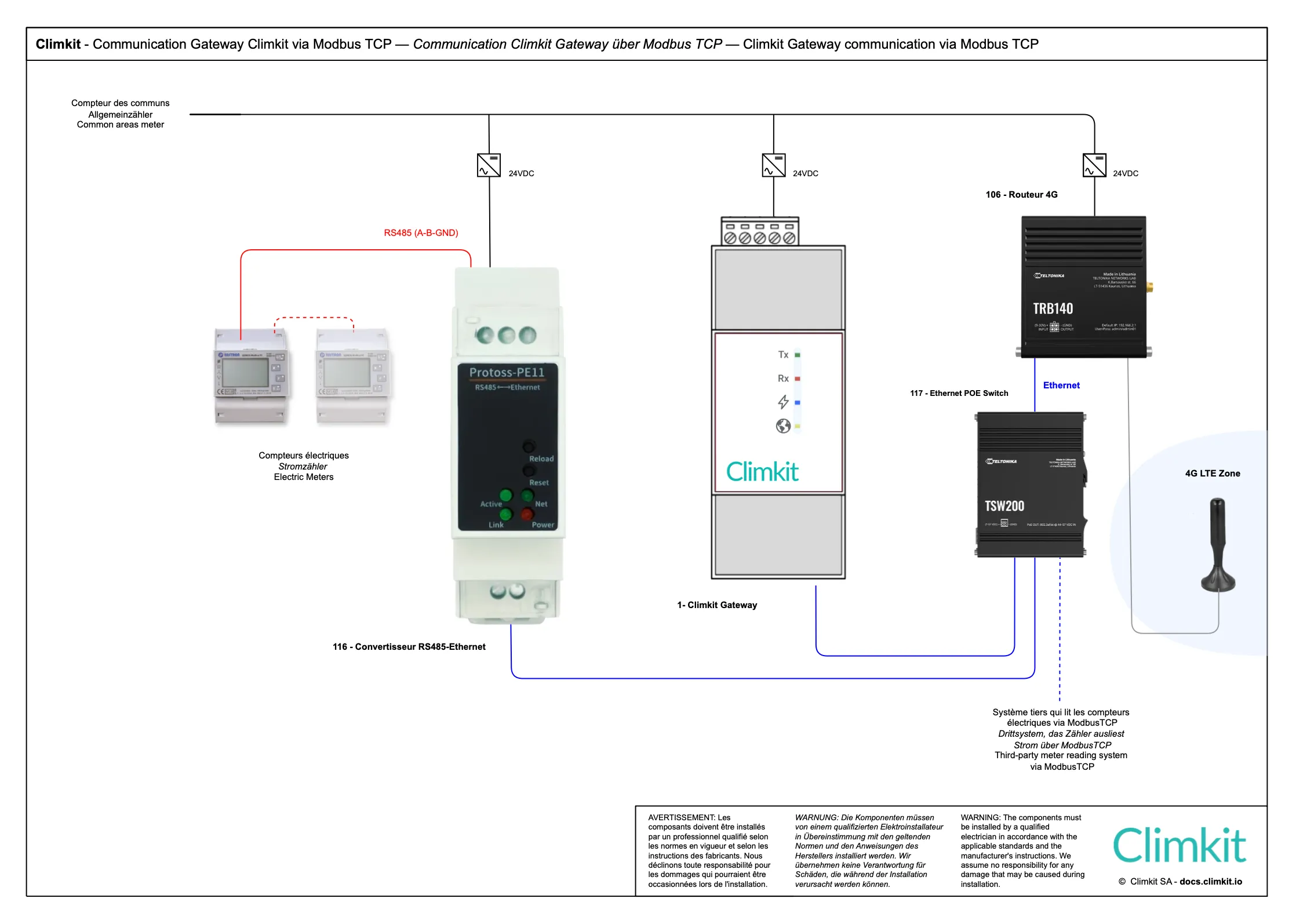
RS485-Ethernet Converter (Modbus RTU to Modbus TCP)
The RS485-Ethernet converter allows for switching from an RS485 bus network to a TCP/IP network, enabling the reading of Modbus RTU devices via Modbus TCP.
The model provided is a Protoss-PE11, delivered configured and with its 24V DC DIN rail power supply.
It can be used to read electricity meters directly via the 4G Router (see Cloud Gateway diagram) or to connect electricity meters distributed across different electrical cabinets on the same site, all linked together by a local IP network (see Microgrid diagram). In this case, a single Climkit Gateway is sufficient to read all the site's meters via Modbus TCP.
3. Other connection options
Connecting several buildings belonging to the same site
The RS485-Ethernet converter can be used in two main configurations:
- Cloud Gateway configuration: To read electricity meters directly via the 4G Router (see Cloud Gateway diagram).
- Microgrid configuration: To connect electricity meters distributed across different electrical cabinets on the same site, all linked together by a local IP network (see Microgrid diagram). One single Climkit Gateway is then sufficient to read all the site's meters via Modbus TCP.
- In cases where other service providers need to read the same Modbus meters, installing an RS485-Ethernet converter allows for simultaneous reading requests, which is not possible on a simple RS485 bus network.
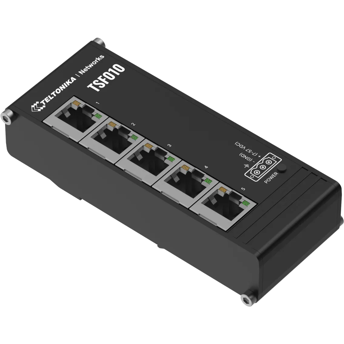
Standard Ethernet Switch
To connect additional Ethernet devices, a switch is required.
Climkit offers a compact switch that installs directly on a DIN rail, accompanied by a 24V power supply (1 module).
With its 5 ports, it allows for connecting the photovoltaic inverter, battery monitoring, or other devices.
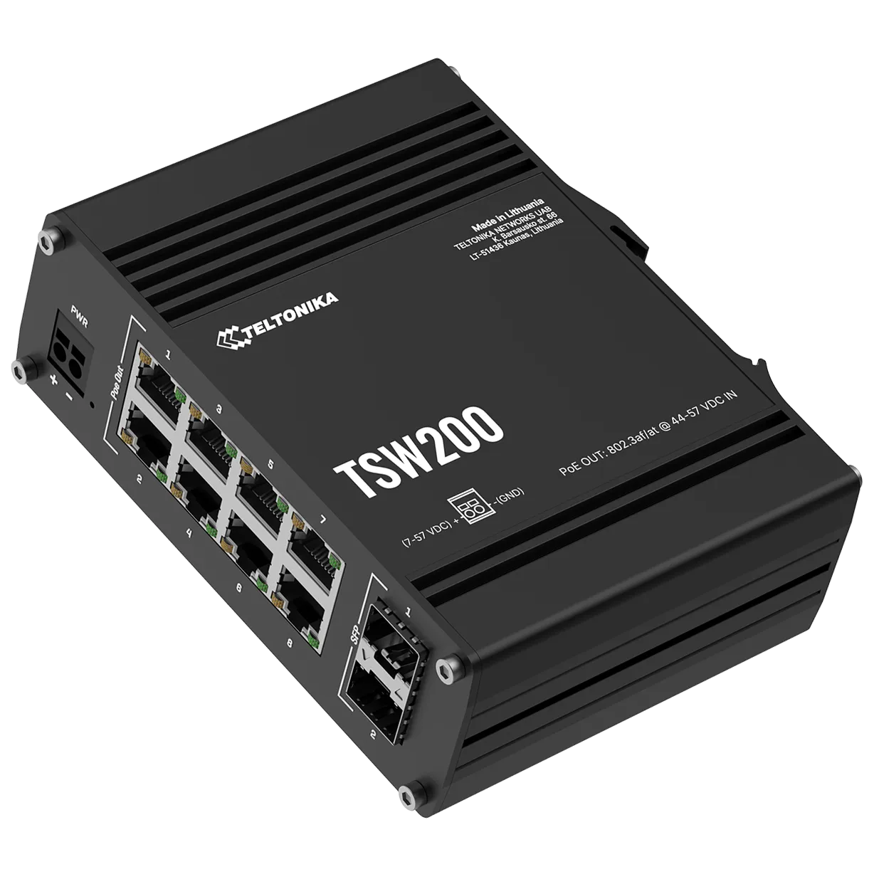
PoE Switch
For Ethernet equipment requiring PoE power, a PoE switch is required.
It allows for direct powering of the gateway, the controller, and Wi-Fi access points via the Ethernet cable, without additional power supply.
Furthermore, the SFP ports allow for interconnecting several buildings on a site (see Microgrid diagram) via fiber optics through a single internet router.
Model provided: Teltonika TSW200 (or equivalent) - 8 Ethernet PoE ports + 2 SFP fiber optic ports.
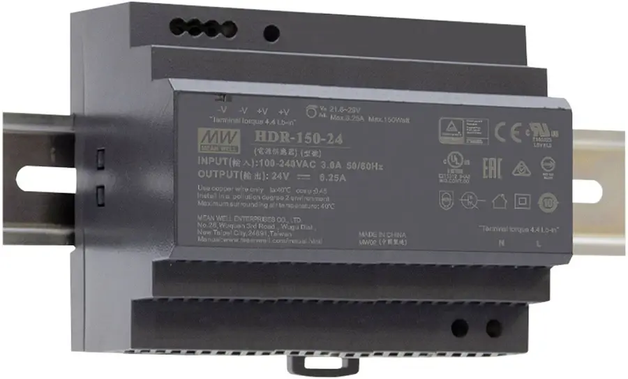
The switch is delivered with a DIN rail support and its 48V DC 150W DIN power supply.