Virtual assistant
Installer
Planning
Installer startup guide (read first)
Global planning of a Climkit site
Process for setting up a Climkit site
Plan the connection of the Climkit Gateway and network connectivity
Plan electricity management
Plan the management of electric vehicle charging stations
Schedule the management of heating costs, water, and ancillary costs
Plan collective laundry management
Plan to manage eBike charging
General terms and conditions of sale
Platform configuration
Request for an Installer account
Creation of a new site
Add the router (4G or LAN)
Adding the Climkit Gateway
Adding electricity meters
Save the Photovoltaic installation information
Save the battery info
Adding charging stations
Add the OCPP Remote Electric vehicle charging station
Add the 4-relay I/O module
Adding RFID readers
Adding heat and water meters
Installation and connection
Install the 4G Router
Install the LAN router
Installing the Climkit Gateway
Install the RS485-Ethernet converter
Install the M-Bus converter
Install the standard Ethernet switch
Install the PoE Ethernet switch
Install Wi-Fi Access points
Install the electricity meters
Install the charging stations
Install the heat and water meters
Install the RFID reader
Install the three-phase Relay meter
Installing the Shelly relay meter
Install the 4-relay I/O module
Verification and testing
Owner
Administrative setup
Getting started guide - administrative setup
Form - 1. Contact details
Form - 2. Solutions
Form - 3. Billing rates
Contract and documents to be completed
Online account for owners
Information flyers for consumers
Online Access, RFID badge and charging stations
FAQ and other information
Resident
Account and app
Electricity invoice
Electric vehicle charging station
Building laundry room
Electric vehicle charging (eBike)
Platform
Platform Access
Terminology
Site
Settings
Creation/editing of a note or an issue to be addressed
Close an issue to be processed
Site statuses
Add/Modify building(s)
The steps for setting up a site
Delete/deactivate a site
Add/Edit equipment
Edit the basic information of a site
Equipment
Add/modify a gateway
Add/modify a router
Add/modify an electricity meter
Bulk insert meters
Bulk assign meters to a gateway
Add/modify a distribution zone
Add/edit a charging station
Add/modify a thermal meter or water meter
Add/edit a DSO meter (FTP transfer)
Connect remotely to a Climkit gateway
Administration
Stakeholders
Management terms
View the site management conditions
Enabling/disabling a solution
Configuration of the operating method
Visualize the financial conditions
Creation/edition/addition of a financial condition
Deletion of a financial condition
Accounts
Create a consumer account
Create a contact
Visualize and download account invoices
Send Platform Access to a contact
Add/modify the postal billing address
Link an existing account to a site
Change the correspondence method
Rates and billing points
Creation/editing of a billing point
Registering a move (transfer)
Assignment of an account to a billing point
Add/modify the default charge advance payment of a billing point
View site billing rates
Editing a consumption tariff
Creation/editing of a consumption tariff
Creation/editing of a consumption tariff component
View fixed rates and subscriptions
Customize invoice line item labels/titles
View the Financial conditions billed to the billing points
RFID badges
Accounting
Tools
Meter inspection
Visualization
Expense statements
Introduction to the Expense statement generation tool
Create/edit an accounting period for expense statements
Modify the expense statements settings
Add/modify a general invoice for an expense statement
Edit the advance payments collected for an expense statement
Special feature of room heating and hot water production fees
Verify and download meter readings for the expense statement period
Make the cost allocation and generate the expense statements
Export individual consumptions for the expense statements period
API
Table of Contents
- Categories
-
- Module I/O relay
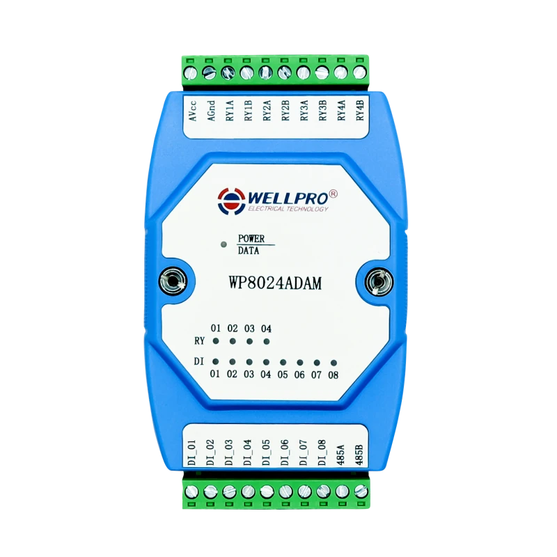
Module I/O relay
Module I/O 4 Relays 8 DI
The WP8024 I/O module is supplied with a 24V DC DIN rail power supply and connects to the Climkit Gateway via RS485-Modbus (like electricity meters).
It features 4 relays that can be used to control equipment such as water heaters, heat pumps, pool pumps, etc.
Potential-free contacts (e.g., SG-ready for the heat pump) can be connected directly to one of the module's relays.
In the case of a water heater, the module's relays control control relays (contactors) which, in turn, switch on the water heater.
A three-phase water heater resistance can be connected with an independent relay per phase to allow staged switching and maximize self-consumption even with low photovoltaic production.
If 4 relays are not sufficient, it is possible to connect multiple modules to the Gateway.
It also has 8 digital inputs (DI) which are, for example, used to detect the signal from a DSO meter for load shedding of charging stations.
Supplied with a 24V DC DIN rail power supply.
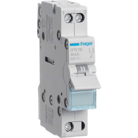
3-Position Switch
It is recommended to install a 3-position switch between the relay module and the equipment being controlled to allow manual switching of the latter.
Positions:
- Up (I): Automatic, controlled by the relay module and the optimization system
- Middle (0): Forced Off
- Down (II): Forced On
Typical model: Hager SFB116