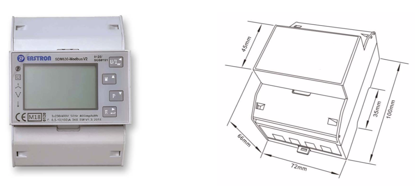
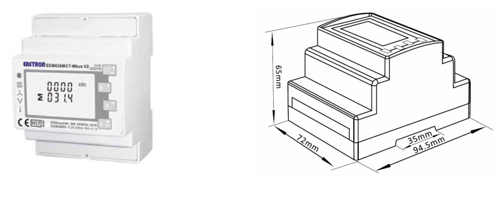
Climkit generally supplies the Eastron SDM630Modbus meter, but other models with similar features and size may be delivered depending on current stock.
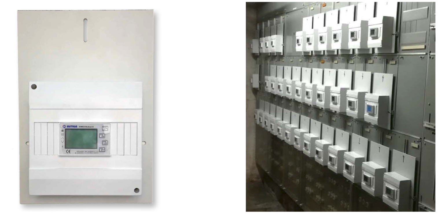
For panels with GRD meter plates, DIN rail housings with mounting plates can be ordered.
DIN rail housing on T mounting plate (H: 36cm, W: 21cm)
4. Installation and configuration
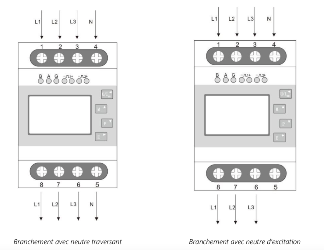
Direct meter
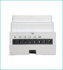
Connect the phases from the grid side at the top (L1, L2, and L3).
Connect the consumer (or photovoltaic inverter) from the bottom (L1, L2, and L3).
Connect the neutral wire at the top and/or bottom of the meter (N).
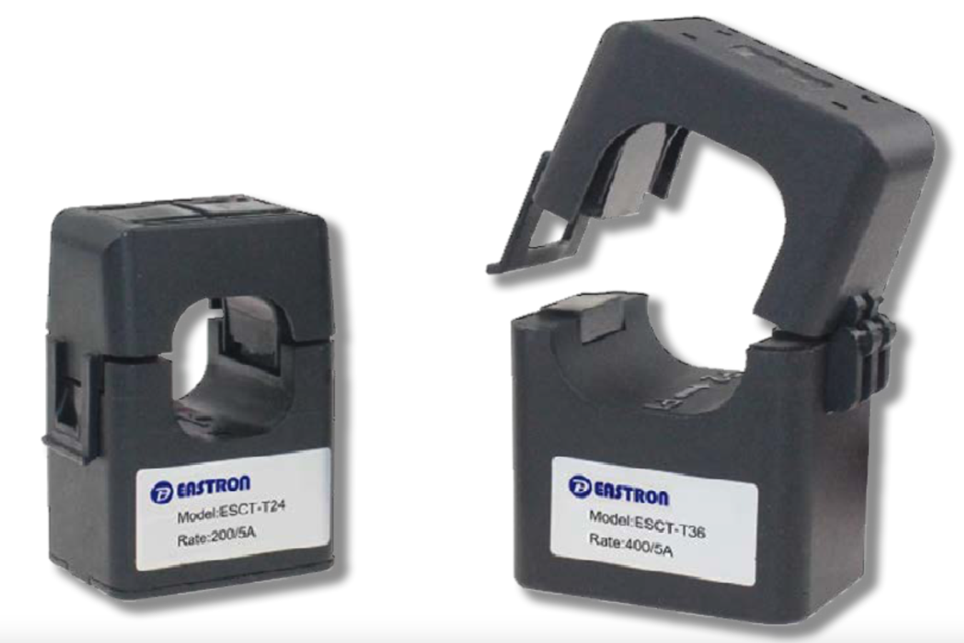
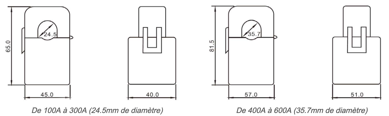
Indirect meter and Current Transformer (CT)
Warning! It is essential to perform the configuration procedure below immediately upon installing the meter. Otherwise, the measurement will be incorrect!
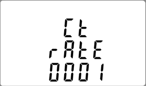
CT Ratio: The CT ratio (CT rate) equals the primary current of the CT divided by its secondary current. The primary current is indicated on the CT. The secondary current is 5A.
Caution! The ratio can only be set once on a MID-certified meter. If an error occurs, the meter must be replaced!
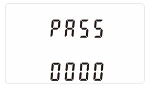
Press the "E" key for 3 seconds and enter the default password (1000) using the "P" and "M" keys. Confirm by pressing and holding "E".Navigate to "CT rate".Press the "E" key for 3 seconds and enter the CT rate corresponding to the primary current of the installed CT according to the table below. Confirm by pressing and holding "E".
Primary Current
CT Rate (Ratio)
100 A
20
200 A
40
400 A
80
600 A
120
800 A
160
1000 A
200
1500 A
300
2000 A
400
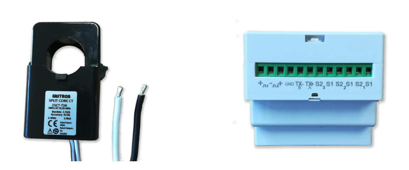
Voltage Measurement (U): Connect the neutral wire to N and each phase to L1, L2, and L3. Also connect LA to L1 and NA to N to power the meter.
Current Measurement (I): Open and securely close each CT on each phase cable whose current needs to be measured. Connect the S1 (white) and S2 (black) wires from the CT to the top of the meter for each phase.
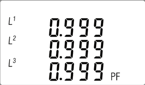
Voltage and Current Connection Verification: Press the "M" button until the Power Factor (PF) for each phase L1, L2, and L3 is displayed. The displayed values should be close to 0.9. If this is not the case, the voltage measurement and current measurement are not on the same phase. Move the S1 and S2 pairs to another phase until a correct value is obtained.
To avoid disturbances during this check on a consumption or input meter, momentarily trip the site's photovoltaic inverters.
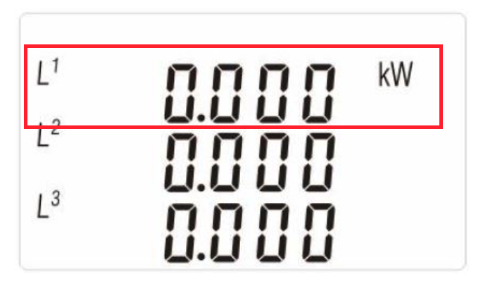
CT Direction Verification: Press the "P" button until the instantaneous active power (kW) for each phase L1, L2, and L3 is displayed. The values must be positive (consumption meter) or negative (production meter) indicated by the "-" sign. Always verify the input meter with the site inverters tripped to obtain positive values. Do not rely on the arrow indicated on the CT. If the indicated value is in the wrong direction, reverse the S1 and S2 wires for that phase.
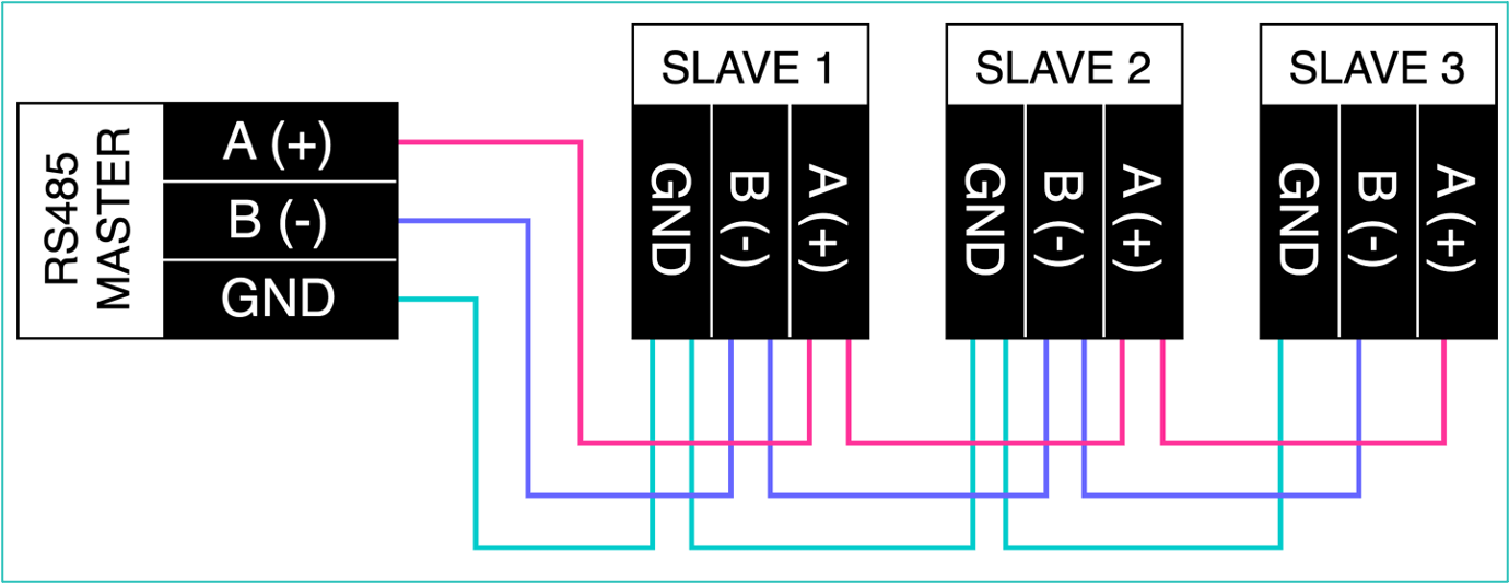
Communication bus connection
The meters (Slaves) are connected via an RS485 bus network to the gateway (Master) according to the diagram below.
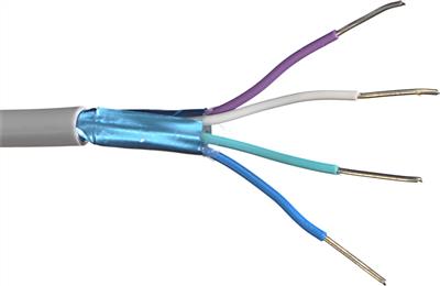
Bus connection requires careful and rigorous work. For new panels, it is recommended to do it in the workshop and use a shielded U72 type cable 4 x 0.8mm2.