Virtual assistant
Installer
Planning
Installer startup guide (read first)
Global planning of a Climkit site
Process for setting up a Climkit site
Plan the connection of the Climkit Gateway and network connectivity
Plan electricity management
Plan the management of electric vehicle charging stations
Schedule the management of heating costs, water, and ancillary costs
Plan collective laundry management
Plan to manage eBike charging
General terms and conditions of sale
Platform configuration
Request for an Installer account
Creation of a new site
Add the router (4G or LAN)
Adding the Climkit Gateway
Adding electricity meters
Save the Photovoltaic installation information
Save the battery info
Adding charging stations
Add the OCPP Remote Electric vehicle charging station
Add the 4-relay I/O module
Adding RFID readers
Adding heat and water meters
Installation and connection
Install the 4G Router
Install the LAN router
Installing the Climkit Gateway
Install the RS485-Ethernet converter
Install the M-Bus converter
Install the standard Ethernet switch
Install the PoE Ethernet switch
Install Wi-Fi Access points
Install the electricity meters
Install the charging stations
Install the heat and water meters
Install the RFID reader
Install the three-phase Relay meter
Installing the Shelly relay meter
Install the 4-relay I/O module
Verification and testing
Owner
Administrative setup
Getting started guide - administrative setup
Form - 1. Contact details
Form - 2. Solutions
Form - 3. Billing rates
Contract and documents to be completed
Online account for owners
Information flyers for consumers
Online Access, RFID badge and charging stations
FAQ and other information
Resident
Account and app
Electricity invoice
Electric vehicle charging station
Building laundry room
Electric vehicle charging (eBike)
Platform
Platform Access
Terminology
Site
Settings
Creation/editing of a note or an issue to be addressed
Close an issue to be processed
Site statuses
Add/Modify building(s)
The steps for setting up a site
Delete/deactivate a site
Add/Edit equipment
Edit the basic information of a site
Equipment
Add/modify a gateway
Add/modify a router
Add/modify an electricity meter
Bulk insert meters
Bulk assign meters to a gateway
Add/modify a distribution zone
Add/edit a charging station
Add/modify a thermal meter or water meter
Add/edit a DSO meter (FTP transfer)
Connect remotely to a Climkit gateway
Administration
Stakeholders
Management terms
View the site management conditions
Enabling/disabling a solution
Configuration of the operating method
Visualize the financial conditions
Creation/edition/addition of a financial condition
Deletion of a financial condition
Accounts
Create a consumer account
Create a contact
Visualize and download account invoices
Send Platform Access to a contact
Add/modify the postal billing address
Link an existing account to a site
Change the correspondence method
Rates and billing points
Creation/editing of a billing point
Registering a move (transfer)
Assignment of an account to a billing point
Add/modify the default charge advance payment of a billing point
View site billing rates
Editing a consumption tariff
Creation/editing of a consumption tariff
Creation/editing of a consumption tariff component
View fixed rates and subscriptions
Customize invoice line item labels/titles
View the Financial conditions billed to the billing points
RFID badges
Accounting
Tools
Meter inspection
Visualization
Expense statements
Introduction to the Expense statement generation tool
Create/edit an accounting period for expense statements
Modify the expense statements settings
Add/modify a general invoice for an expense statement
Edit the advance payments collected for an expense statement
Special feature of room heating and hot water production fees
Verify and download meter readings for the expense statement period
Make the cost allocation and generate the expense statements
Export individual consumptions for the expense statements period
API
Table of Contents
- Categories
-
- Self-consumption optimization
Self-consumption optimization
1. Self-consumption Optimization
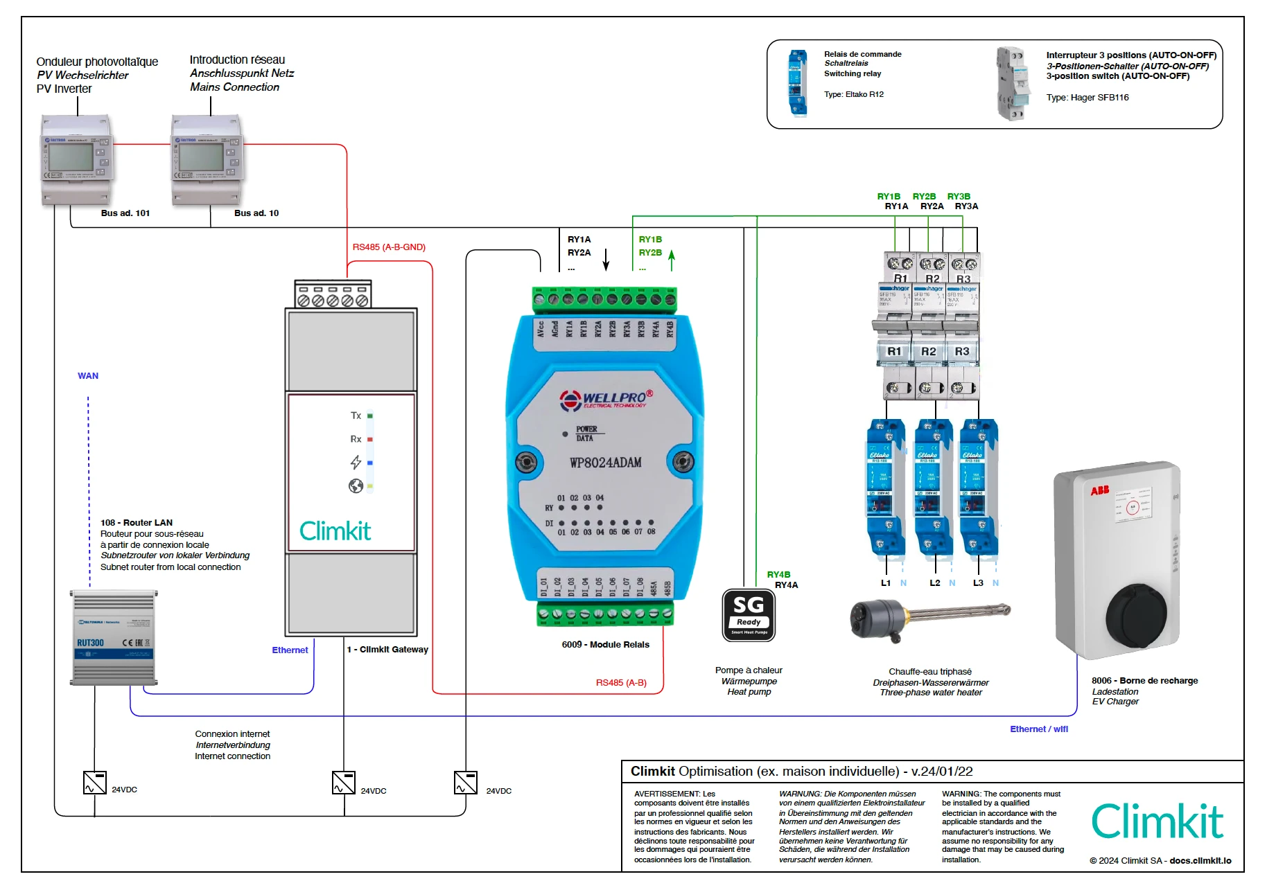
The Climkit optimization system allows for increasing the self-consumption rate of a photovoltaic installation by controlling certain appliances based on solar energy production.
The surplus fed back into the electrical grid is thus limited, and autonomy is also gained by, for example, producing hot water with solar energy.
Appliances (water heaters, heat pumps, radiators, pool pumps, etc.) are controlled via a relay.
It is also possible to control certain electric vehicle charging stations (via Wifi or Ethernet).
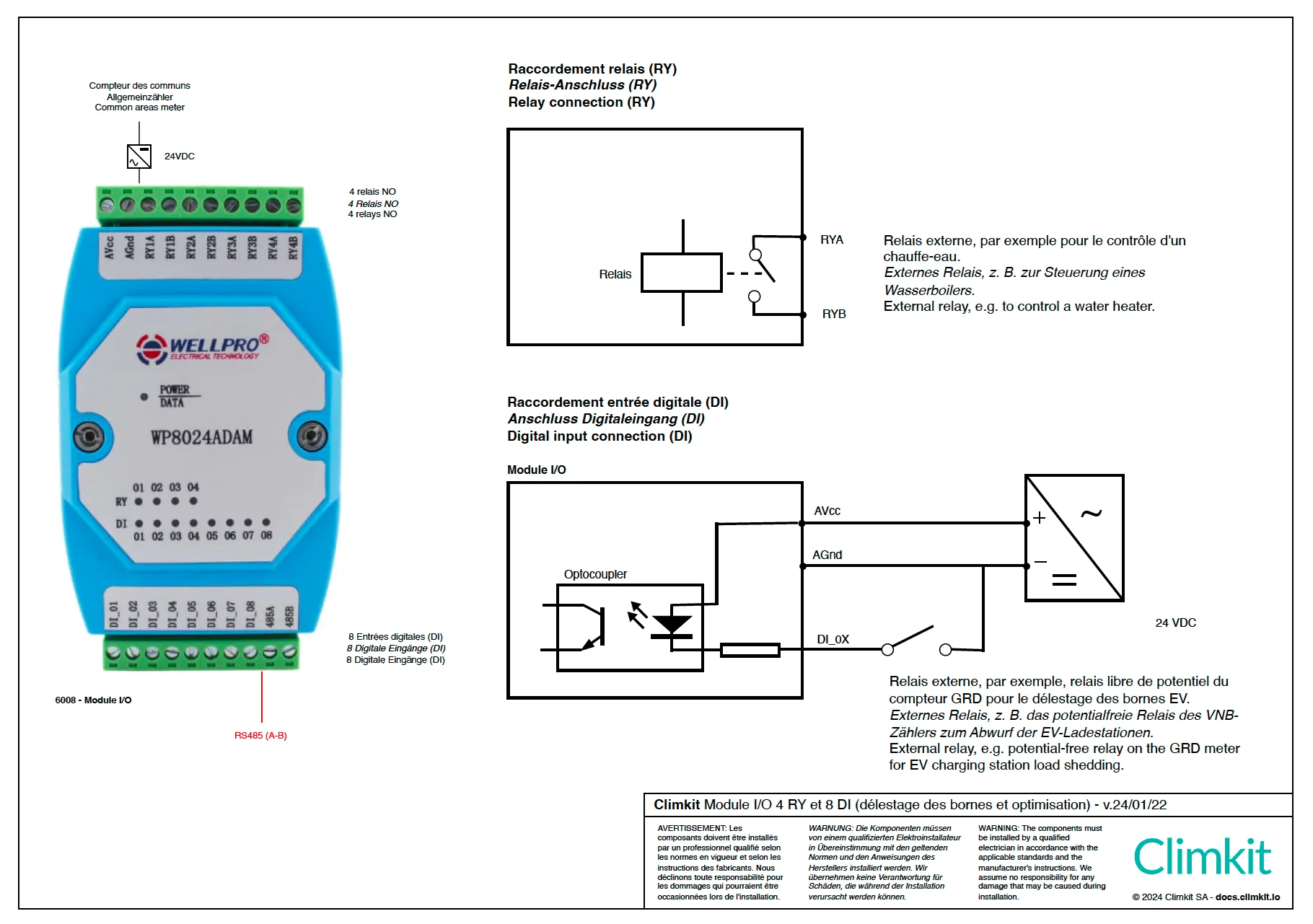
Detailed connection of a relay to the I/O module
The relay I/O module has 4 relays.
2. Algorithm Operation
The system evaluates the electrical power fed back to or drawn from the electrical grid every minute.
In case of fed-back surplus, it activates the different configured and connected appliances.
For example, if there is a surplus greater than or equal to 1000 W, it activates the 1000 W water heater.
Conversely, if there is no longer a surplus and energy is being drawn from the grid, the system deactivates the necessary appliances to limit the draw.
Appliances are activated and deactivated according to the selected operating modes, for example in "Solar only" or "Solar and timer" mode. See Configuration below.
It is not possible to set activation or deactivation priorities among the appliances; these are controlled solely based on their nominal power to maximize self-consumption.
To be as flexible as possible, it is recommended to connect appliances with the lowest possible power rating so that they are activated with even a small surplus.
For example, the 3 phases of a 3000 W water heater can be connected to an independent relay to benefit from three 1000 W steps.
Specific Notes
Minimum power and number of phases for a charging station
Generally, an electric vehicle requires a minimum of 6A to start charging. Some vehicles require 8A or 10A. A minimum set below these values can cause an error on the vehicle.
This 6A minimum is the same for single-phase and three-phase systems, meaning 1380 W for single-phase 230V or 4140 W for three-phase.
Consequence for optimization: a vehicle connected to a three-phase charging station requires a minimum solar surplus of 4140 W for the system to initiate charging.
In the case of small photovoltaic installations (5-8 kWp), the surplus required to activate the charging station will only be available in summer and during the middle of the day.
In these cases, it is recommended to connect the 3 phases of the charging station to 3 relays or at least to 3 independent switches so that the user can easily switch from one phase to three phases. See the diagram above.
When changing the number of phases of the charging station, you must turn off the main circuit breaker of the station, connect or disconnect the connection phases, and then turn the station back on.
The optimization system does not allow for phase control and automatic switching from a single-phase load to a bi- or three-phase load.
Vehicle Standby
When a vehicle is connected to the charging station but the solar surplus is insufficient to initiate charging, the vehicle remains in standby until the station supplies it with electricity.
In some cases, the vehicle may enter deep sleep after some time, and when the station supplies it with electricity again, charging will not start until the vehicle is "woken up" by the user.
This often happens when the vehicle is plugged in during the evening and the solar surplus will only be available the next morning.
Some vehicles can be updated to prevent these unexpected standby states. Consult the vehicle manufacturer.
Older Vehicles
Some older vehicles (pre-2012-2014) do not support power variation during charging and are therefore not controllable via the optimization system.
Heat Pumps (SG-Ready)
Most modern heat pumps (HP) are equipped with a potential-free contact which, when closed, sends an instruction to the HP's internal management system.
Generally, the HP can be configured to increase its heating setpoint or produce more hot water when this contact is closed.
By connecting a relay from the optimization system to this contact, the HP's activation can be forced when the photovoltaic installation produces surplus energy.
Consult the HP manufacturer.
Connection of a Three-Phase Water Heater
Many water heater elements are connected with 3 wires without a neutral conductor. Therefore, a neutral conductor is necessary to control each phase individually.
Otherwise, at least two phases are always required for it to be switched on.
Two relays can then be used to control: phase 1 and 2 with the first relay, and 1 and 3 with the second.