Virtual Assistant
Installer
Getting Started Guide
Solutions and Documentation Structure
Material ordering and commissioning
General Sales Terms and Conditions and Warranty
Connection Schemes
Gateway and Communication
Community - Electric Metering - RCP
Heating - Heating and Water Metering
Mobility - EV Charging Stations
Washaccess - Laundry Manager
EBike - Charging Electric Bicycles
Optimization of self-consumption
Energy monitoring of the building
Equipment and Installation
Gateway Climkit
4G Router
LAN Router
RS485-Ethernet Converter
Switch ethernet DIN POE
WiFi Network
Electric Meters
MBus-RS485 converter
Heating & Water Meters
EV Charging Stations
Relay I/O Module
RFID Readers
Relay Meters
Storage system (battery)
Configuration and commissioning
Commissioning
Start-Up Guide for Commissioning
Add a router to a site
Add a Climkit Gateway to a Site
Configuration of Electric Meters
Charging Station Configuration
Configuration of heating and water meters (MBus)
Optimization via Relay and EV Charging Stations
Verification of Meter Connections
Advanced Configuration
Gateway Configuration
RFID Reader and Meter-Relay Configuration
IP network configuration and routers
RS485 to Ethernet TCP/IP Converters
Configure Teltonika RUT241
Configuring Display Screens
Modbus Meter Configuration
Data Counting Processing
Meter Read Manually
Inepro PRO380 Meters and Various
Configuration of ABB charging station
Wallbox Configuration
Firewall Rules for Climkit Gateway
Configuration of Schneider EVlink Pro AC charging station
Zaptec Terminal Configuration
Owner
Administrative setup
Getting Started Guide - Administrative Setup
Form - 1. Contact Details
Form - 2. Solutions
Form - 3. Rates
Contract and documents to complete
Online Account for Homeowners
Information Flyers for Consumers
Online access, RFID badge, and charging stations
FAQ and Other Information
Resident
Platform
Access to the platform
Terminology
Site
Parameters
Creation/Editing of a Note or an Issue to be Addressed
Close an issue to be addressed
The states of a site
Add/Edit Building(s)
The steps to set up a website
Remove/Disable a Site
Add/Edit Equipment(s)
Edit Basic Site Information
Equipment
Add/Modify a Gateway
Add/Edit a Router
Add/Modify an Electricity Meter
Mass Insertion of Meters
Bulk Assign Counter to a Gateway
Add/modify a distribution area
Add/Modify a Charging Station
Add/Modify a Thermal or Water Meter
Add/Edit a DSO Meter (FTP Transfer)
Connecting Remotely to a Climkit Gateway
Administration
Speakers
Management Conditions
Visualizing Site Management Conditions
Activation/Deactivation of a Solution
Configuration of the Operating Method
Visualizing Financial Conditions
Creation/Editing/Adding a Financial Condition
Removal of a financial condition
Accounts
Create a Consumer Account
Create a contact
View and Download Invoices from an Account
Send platform access to a contact
Add/modify billing address
Link an Existing Account to a Site
Change the Matching Method
Rates and Billing Points
Creation/Editing of a Billing Point
Registering a Move (Transfer)
Account allocation to a billing point
Add/modify the default charge deposit of a billing point
See the prices on the consumption site
Editing a consumption rate
Creation/Editing of a Consumption Rate
Creation/Editing of a Consumption Rate Component
See Fixed Rates and Subscriptions
Customize Invoice Line Item Labels/Titles
See the Financial Conditions Invoiced at the Billing Points
RFID Badges
Accounting
Tools
Meter Control
Visualization
Expense Reports
Introduction to the Expense Tracking Tool
Create/modify a fee countdown period
Modify Fee Count Settings
Add/Modify a General Expense Invoice in an Expense Report
Edit the deposits received from an expense statement
Specificity of heating and hot water production costs
Check and download meter readings for the billing period
Distributing and Generating Expense Summaries
Exporting Individual Consumption for the Expense Settlement Period
API
- Categories
- Installer
- Connection Schemes
- Mobility - EV Charging Stations
Mobility - EV Charging Stations
1. Standard Connection Diagram
The Climkit Mobility system involves the installation of smart charging stations that communicate with the Climkit Gateway via the OCPP protocol.
Through this communication and the installation of continuously monitored meters, the Climkit Gateway can regulate the available power allocated to the stations and also manage user access, identified via RFID badges.
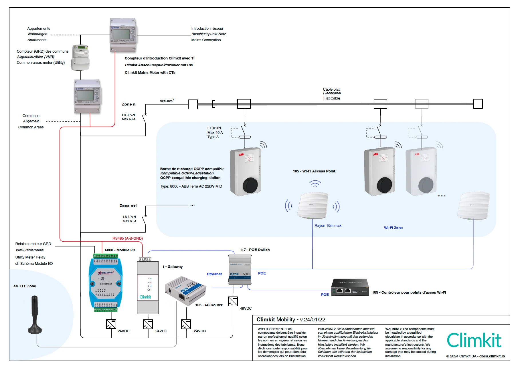
Connection in a RCP
In a Climkit RCP (see Community - Electric Metering - RCP), a meter is installed on each distribution zone branch (flat cable). This meter is never installed behind the common meter.
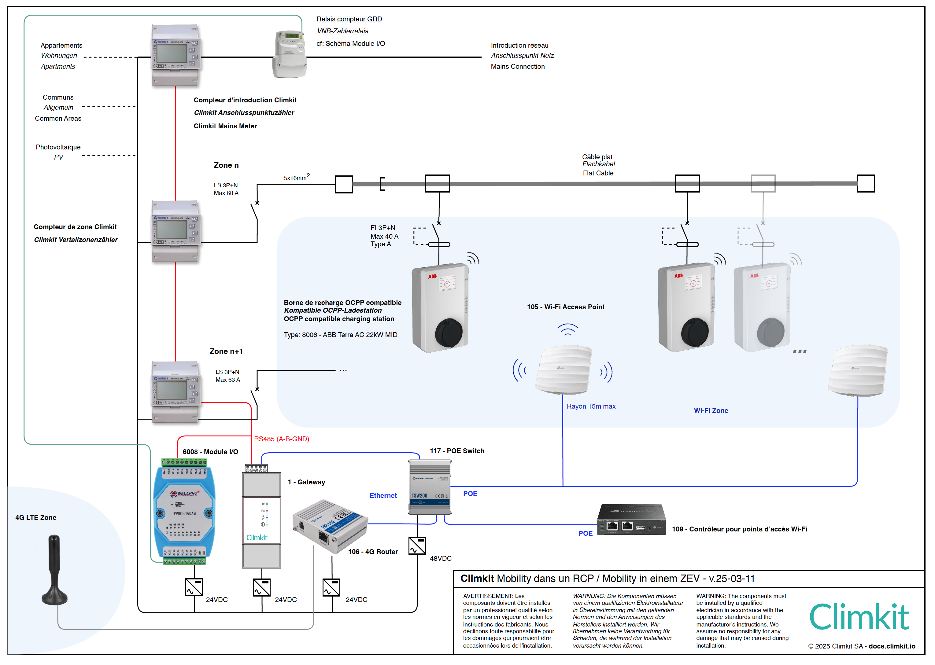
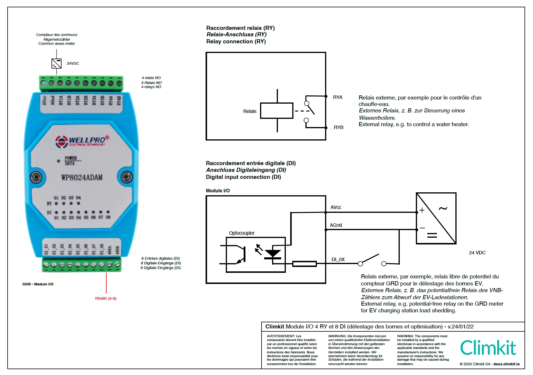
Connection of the I/O Module
The I/O Module is used to detect a command from the GRD meter for the shedding of the stations.
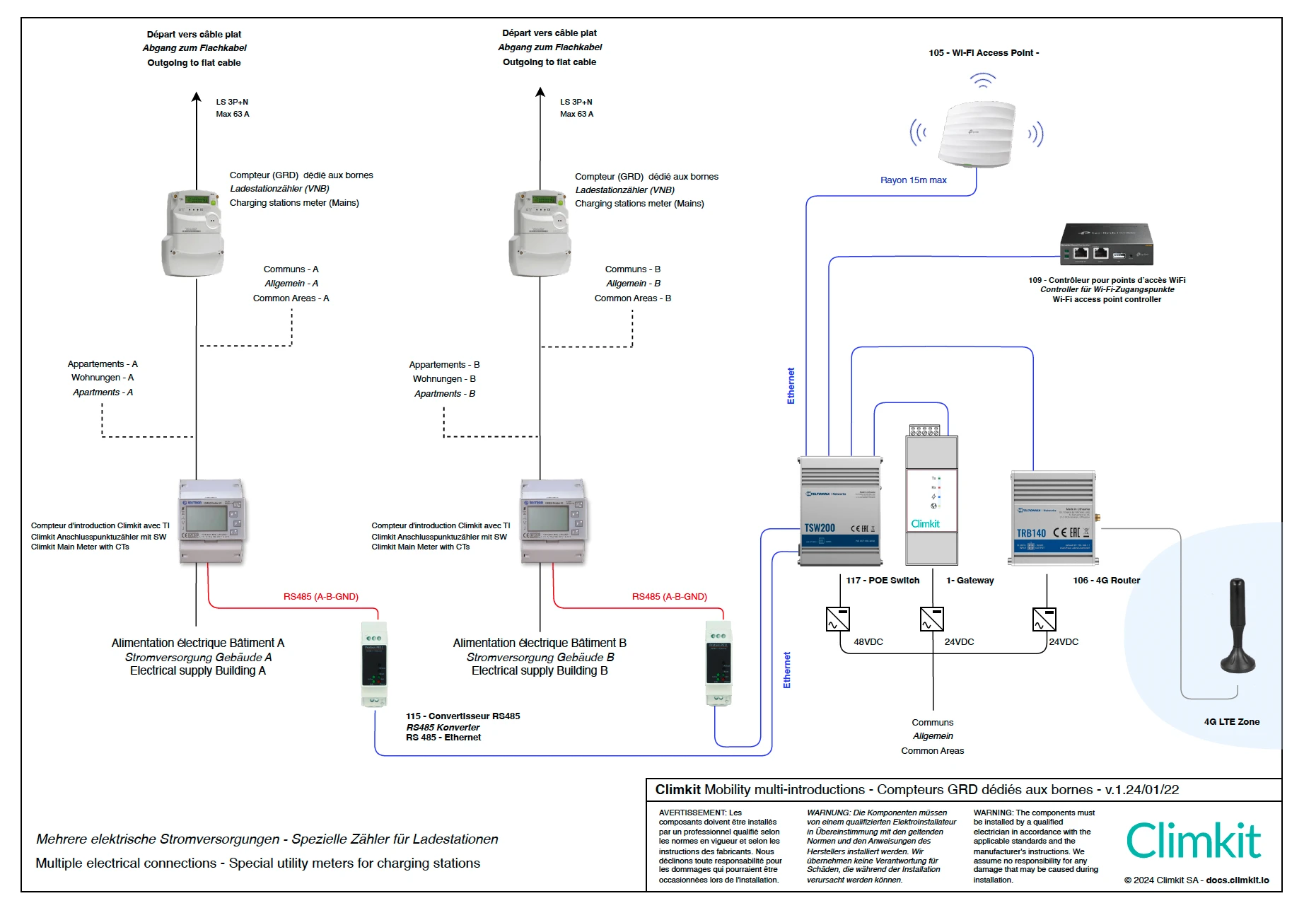
2. Connection Diagram - A Parking Lot and Multiple Introductions
When there are multiple introductions to the network available for the same parking lot, each flat cable branch (63A) is taken from each of the introductions.
Only one gateway and 4G router are needed. Control meters for power regulation are connected to the gateway via an RS485 or IP-ethernet bus using RS485-Ethernet converters.
Option A: Power Supply from the Common GRD Meter
In the diagram below, there are 2 flat cable branches taken behind the common meter of each building.
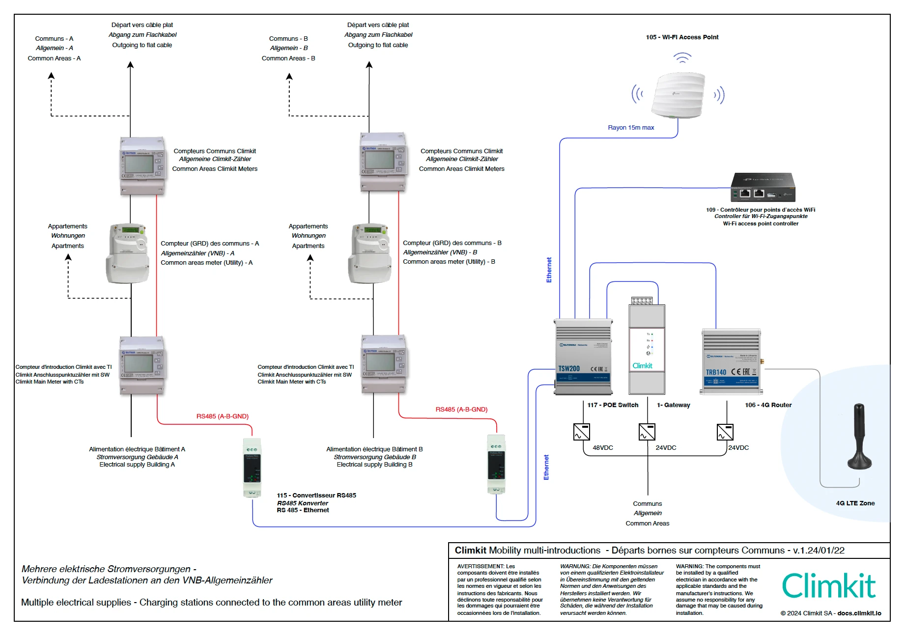
Option B: Power Supply from a Dedicated GRD Meter
In the diagram below, there are 2 flat cable branches taken behind a dedicated GRD meter for the stations for each building. Therefore, it is not necessary to install a Climkit meter on the common branch.
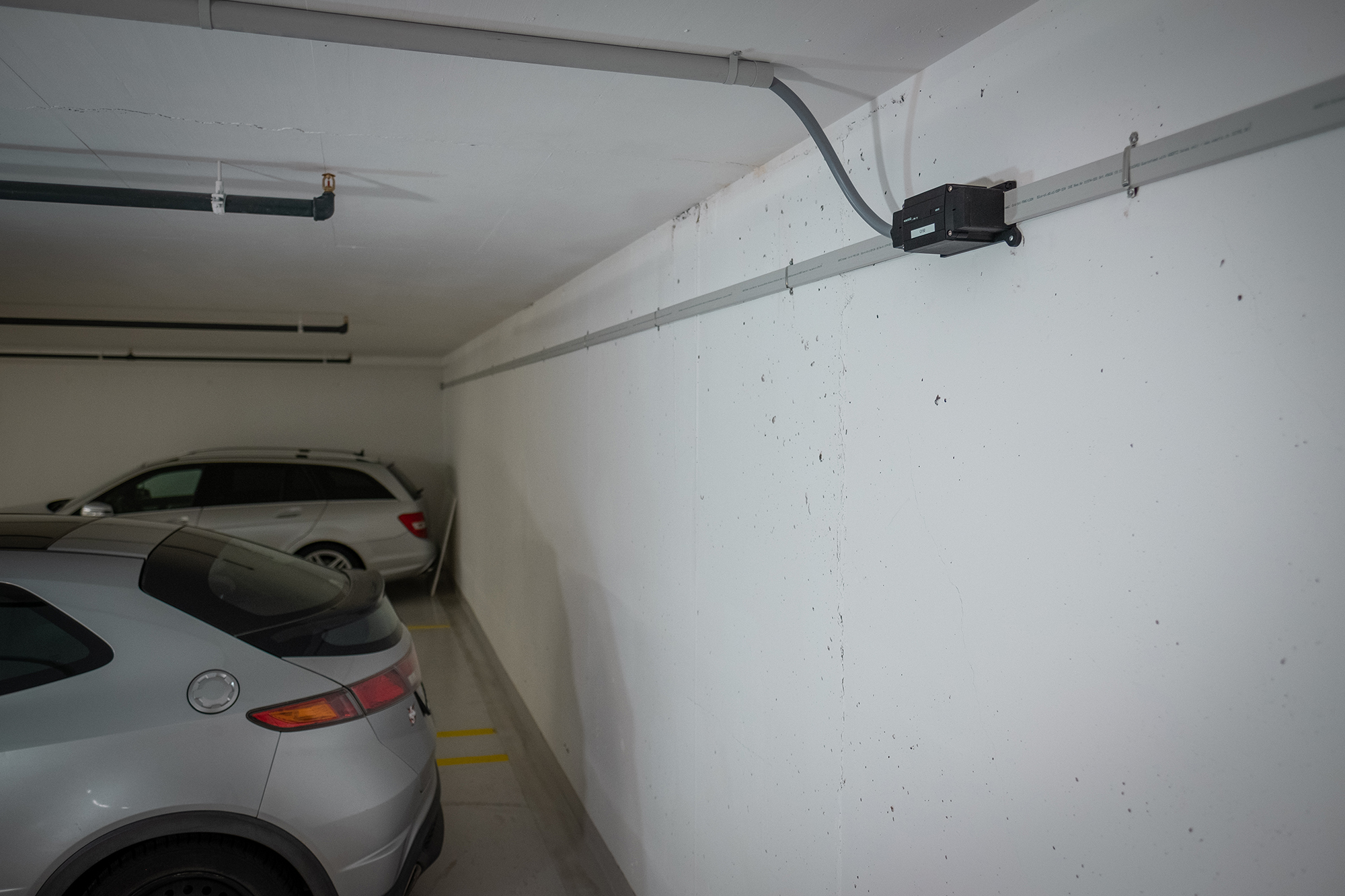
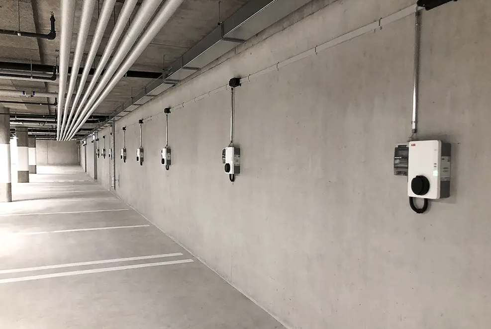
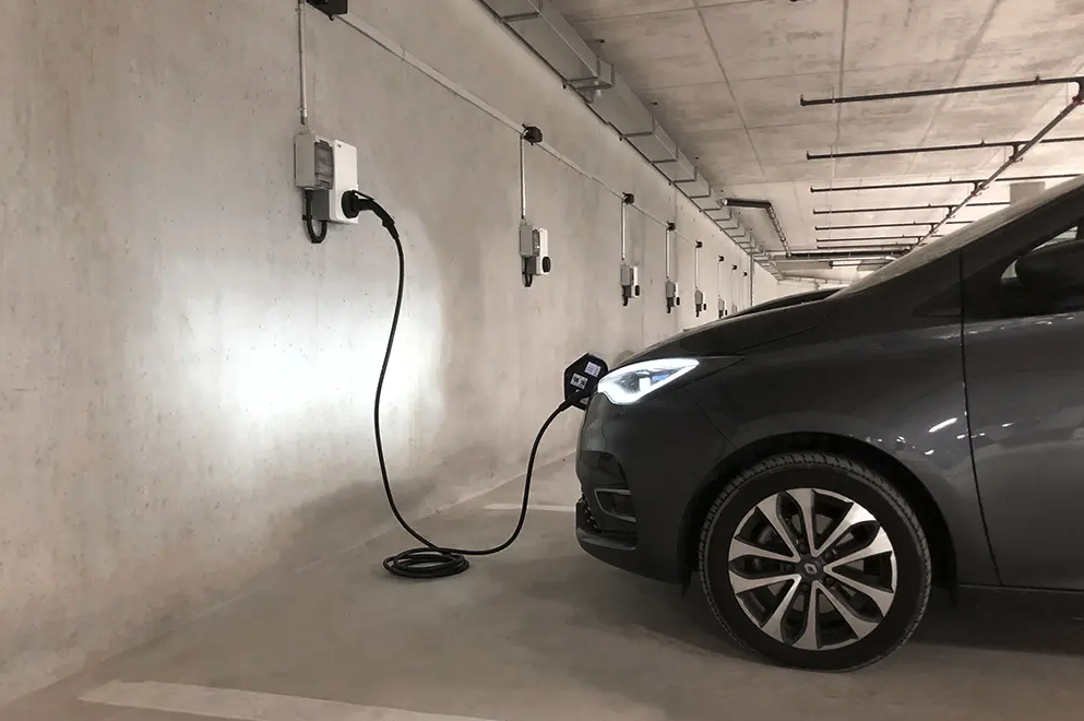
3. Flat Cable in Collective Parking Lots
For small installations, a few stations can be connected individually to the building's electrical panel and connected via ethernet or Wi-Fi.
However, for larger parking lots, it is recommended to install a flat cable to bring electricity to each parking space, thereby facilitating the installation of a charging station as residents wish to equip themselves.
This is what is recommended by level C1 of SIA 2060.
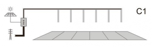
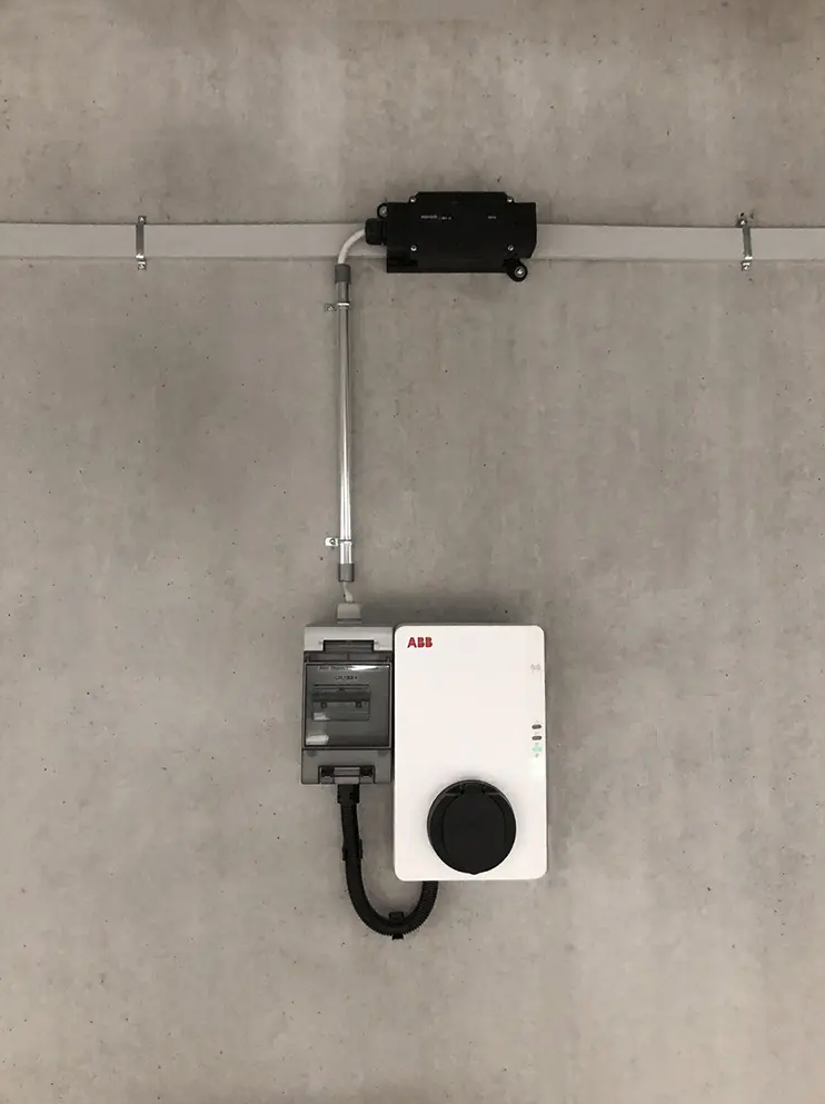
We recommend installing a flat cable of 5x16mm2 from Woertz or Wieland along the parking spaces to be equipped.
The cable is fixed directly with clamps on the wall or ceiling.
Thanks to the IP65 junction boxes with insulating piercing, the stations are then easily connected without cutting or stripping the cable.
The flat cable is powered via a 3P+N LS circuit breaker of max 63A from the electrical panel (provided by the electrical installer).
Although the number of stations per area is unlimited, it is recommended not to connect more than 30.
Each station is then equipped with a type A RCD rated from 16 (11 kW) to 32A (22kW) and connects to the management system via Wi-Fi.
Example of Flat Cable Installation